Dodge Journey: Insulator, engine mount, rear
Removal
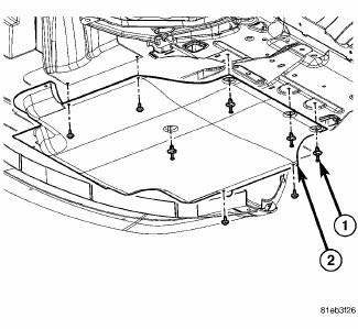
Fig. 234: Belly Pan
1. Remove throttle body air inlet hose and air cleaner housing assembly.
2. Raise the vehicle.
3. Remove the belly pan (2).
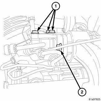
Fig. 235: Identifying Rear Mount Bracket-To-Transaxle Case Bolts
4. Remove three vertical bolts (1) attaching rear mount bracket to transaxle case.
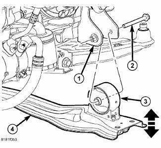
Fig. 236: Front Engine Mount Through Bolt
5. Loosen the front mount through bolt (2).
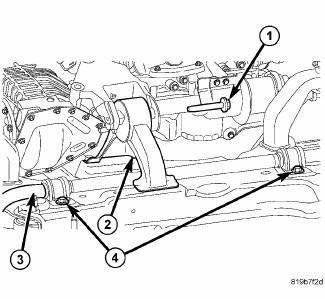
Fig. 237: Rear Engine Mount & Transaxle Bracket
6. Remove rear mount bracket through bolt (1).
7. Remove rear mount bracket from transaxle case.
8. Remove rear isolator to suspension crossmember attaching bolts.
9. Remove rear isolator (2).
Installation
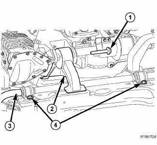
Fig. 238: Rear Isolator On Suspension Crossmember
1. Position rear isolator (2) on suspension crossmember and loosely install bolts.
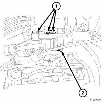
Fig. 239: Identifying Rear Mount Bracket-To-Transaxle Case Bolts
2. Position rear mount bracket on transaxle and install bolts (1). Tighten bolts to 95 N.m (70 ft. lbs.).
3. Tighten rear isolator to suspension crossmember bolts to 61 N.m (45 ft. lbs.).
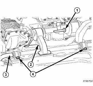
Fig. 240: Rear Isolator On Suspension Crossmember
NOTE: Be sure the weight of the engine is static and in rest position.
4. Install rear mount bracket to rear isolator through bolt (1) and tighten to 75 N.m (55 ft. lbs.).
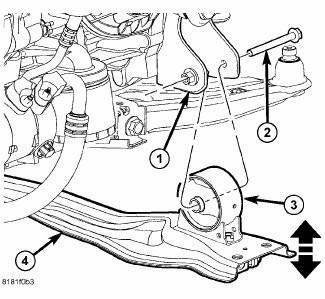
Fig. 241: Front Engine Mount Through Bolt
5. Tighten front mount through bolt (2) to 75 N.m (55 ft. lbs.).
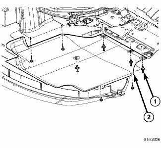
Fig. 242: Belly Pan
6. Install the belly pan (2).
7. Install throttle body air inlet hose and air cleaner housing assembly.
 Insulator, engine mount, left
Removal
Fig. 228: Belly Pan
1. Disconnect and isolate the negative battery cable.
2. Remove throttle body air inlet hose and air cleaner housing assembly.
3. Remove the belly pan (2).
...
 Insulator, engine mount, right
Removal
Fig. 243: Belly Pan
1. Remove the belly pan (2).
Fig. 244: Right Engine Mount
2. Lower vehicle. Remove the load on the engine motor mounts by carefully
supporting the engine assembly ...
See also:
DEPARTMENT OF TRANSPORTATION UNIFORM TIRE QUALITY
GRADES
The following tire grading categories were established by
the National Highway Traffic Safety Administration. The
specific grade rating assigned by the tire’s manufacturer
in each category is sho ...
Operation
The standard front and available rear heating-A/C systems used in this
vehicle are blend-air type systems. In a
blend-air system, a blend-air door controls the amount of conditioned air that
is a ...
Fluid
STANDARD PROCEDURE
FLUID LEVEL AND CONDITION CHECK
FLUID LEVEL CHECK
Fig. 351: Identifying Fluid Level Indicator
- FLUID LEVEL INDICATOR
NOTE: Only transmission fluid of the type labele ...
