Dodge Journey: Installation
FRONT
NOTE: Inspect disc brake pads before installation.
Fig. 169: VENTED BRAKE ROTOR MOUNTING
1. Clean the hub face (1) to remove any dirt or corrosion where the rotor mounts.
2. Install the brake rotor (2) over the studs on the hub and bearing.
Fig. 170: CALIPER/ADAPTER MOUNTING
3. Install the disc brake caliper and adapter bracket assembly (1) over the brake rotor (4) and knuckle (2).
4. Install the mounting bolts (3) securing the caliper adapter bracket to the knuckle (2). Tighten the bolts to 169 N.m (125 ft. lbs.).
Fig. 171: TIRE AND WHEEL MOUNTING
5. Install the tire and wheel assembly (1). Tighten the wheel mounting nuts (3) to 135 N.m (100 ft. lbs.).
6. Lower the vehicle.
7. Pump the brake pedal several times before moving the vehicle to set the pads to the brake rotor.
8. Check and adjust the brake fluid level in the reservoir as necessary.
9. Road test the vehicle and make several stops to seat the brake pads to the rotor.
REAR
NOTE: Inspect disc brake pads before installation. Replace as necessary.
Fig. 172: SOLID BRAKE ROTOR MOUNTING
1. Clean the rotor mounting face of the hub and bearing (1) to remove any dirt or corrosion.
2. Install the brake rotor (2) over the hub and bearing (1).
CAUTION: If the brake rotor or brake pads are being replaced, the rear caliper piston must be seated (bottomed) to compensate for the new brake rotor or lining. Because the parking brake self-adjuster mechanism is attached to the piston, a special seating method is required. The only acceptable method is by rotating the piston back into the bore using Retractor, Special Tool 8807, as described below. Any other seating method will damage the self-adjuster mechanism.
Fig. 173: SEATING PISTON WITH SPECIAL TOOL
3. If necessary, seat (bottom) the caliper piston in the bore as follows:
- Assemble a 3/8 in. drive ratchet handle and an extension (3).
- Insert the extension through Special Tool 8807-1 (2).
- Place Special Tool 8807-2 (1) on the end of the extension.
- Insert lugs on Special Tool 8807-2 into notches in face of caliper piston (5).
- Thread the screw drive on 8807-1 down until it contacts the top of 8807-2 which is against the caliper piston. Do not over tighten the screw-drive. Damage to the piston can occur.
- Turn 8807-2 with the ratchet, rotating the piston in a clockwise direction until fully seated (bottomed) in the bore. It may be necessary to turn 8807-1 with 8807-2 to start the process of piston retraction.
Fig. 174: REAR CALIPER ADAPTER MOUNTING
4. Install the disc brake caliper and adapter bracket (2) over the knuckle and rotor as an assembly.
5. Install the two bolts (1) securing the disc brake caliper and adapter bracket (2) to the knuckle. Tighten the mounting bolts to 100 N.m (74 ft. lbs.).

Fig. 175: TIRE AND WHEEL MOUNTING
6. Install the tire and wheel assembly (1). Install and tighten the wheel mounting nuts (3) to 135 N.m (100 ft. lbs.).
7. Lower the vehicle.
8. Pump the brake pedal several times to ensure the vehicle has a firm brake pedal before moving vehicle.
9. Check and adjust the brake fluid level as necessary.
10. Road test the vehicle and make several stops to wear off any foreign material on the brakes and to seat the brake pads.
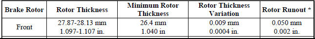
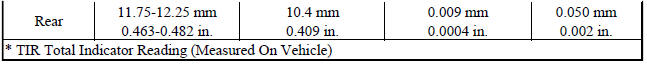
SPECIFICATIONS
NOTE: When refacing a rotor, the required TIR (Total Indicator Reading) and thickness variation limits MUST BE MAINTAINED. Extreme care in the operation of rotor turning (machining) equipment is required.
LIMITS/SPECIFICATIONS
 Removal
FRONT
1. Raise and support the vehicle.
Fig. 163: TIRE AND WHEEL MOUNTING
2. Remove the wheel mounting nuts (3), then the tire and wheel assembly (1).
NOTE: In some cases, it may be necessary ...
 Tubes and hoses, brake
DESCRIPTION
The brake tubes are steel with a corrosion-resistant nylon coating applied to
the external surfaces.
The flex hoses used at each wheel brake are made of reinforced rubber with
fitt ...
See also:
Description, Operation
DESCRIPTION
This vehicle is equipped with a Wireless Ignition Node (WIN) (1). The WIN and
the FOB with Integrated Key
(FOBIK) are the primary components of the keyless ignition system. The only
...
Installation
1. Guide the trailing end of the parking brake cable along the inboard side
of the axle trailing arm up to the
rear brake caliper. Make sure the cable is routed between the brake line and the
tra ...
Valve, oil pressure relief
Removal
Fig. 285: Oil Pressure Relief Valve
- RELIEF VALVE
- SPRING
- RETAINER CAP
1. Remove the oil pan.
2. Remove the pressure relief valve (1) by remove the threaded retaining cap ...
