Dodge Journey: Description
The instrument cluster contains the necessary hardware and software to serve as the vehicle electronic body control module and is commonly referred to as the Cab Compartment Node (CCN). The CCN utilizes integrated circuitry and information carried on the Controller Area Network (CAN) data bus and the Local Interface Network (LIN) data bus, along with several hardwired analog and multiplexed inputs to monitor sensors and switches throughout the vehicle. The CCN also contains various indicators, analog gauges, and a standard bluegreen digital Vacuum Fluorescent Display (VFD) unit. The standard VFD is a fixed segment unit that displays odometer information, automatic transmission gear selector position (PRNDL), and several other indicators, some of which are model dependant.
There are several versions of the CCN offered for this vehicle. These versions accommodate all of the variations of optional equipment for the various markets in which the vehicle is offered. The CCN may also contain a separate reconfigurable blue-green digital VFD unit that has either a Compass Mini-Trip Computer (CMTC) option or an Electronic Vehicle Information Center (EVIC) option. Both of these options provide the outside ambient temperature, compass headings, average fuel economy, and elapsed time. The EVIC option also offers a user interface for customer programmable features, audio system setting displays, numerous textual warnings, reminder indicators, and certain diagnostic information.
A dedicated Light Emitting Diode (LED) soldered onto the circuit board illuminates each indicator in the CCN, except those within a VFD unit. Several dimmable LED units illuminate each gauge dial face for visibility when the exterior lighting is turned on. These LED units are not available for service replacement and, if damaged or ineffective, the entire CCN must be replaced.
The CCN is serviced only as a complete unit and cannot be adjusted or repaired. If a gauge, LED unit, VFD unit, electronic circuit board, circuit board hardware, cluster overlay, or cluster housing is damaged or ineffective, the entire CCN must be replaced. The cluster lens is available for separate service replacement.

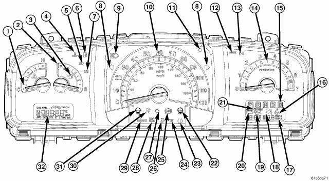
Fig. 1: Mechanical Instrument Cluster
The mechanical instrument cluster is an electromechanical module that receives most of its information directly from the various control modules, with the data bus.
The cluster includes:
- A speedometer (10)
- A tachometer (14)
- A fuel gauge (2)
- A coolant Temperature gauge (1)
The warning and information indicators include the following:
- Coolant temperature warning (4)
- Front fog lamp indicator, front (5), and rear (7) (export only)
- Low fuel (6)
- Turn signal indicator (8)
- High beam (9)
- Vehicle theft security system alarm LED indicator (if equipped) (11)
- All-Wheel Drive (AWD) failure indicator (12)
- Front position lamps (13) (export only)
- Transaxle range indicator (15)
- Seat belt reminder (16)
- Odometer/Trip odometer (17)
- Electronic Throttle Control (ETC) warning lamp (18)
- Low oil pressure (19)
- Charging system (20)
- Cruise (if equipped) (21)
- Trip odometer reset button (cycle to change display; Trip A, Trip B, Outside Temperature for base vehicle) (22)
- Tire Pressure Monitoring (TPM) (23)
- Wait to Start Indicator (Export Diesel) (24)
- Anti-lock brake system (If equipped) (25)
- Electronic Stability Program (ESP) and Traction Control System (TSC) (26)
- Check engine (27)
- Electronic Stability Program (ESP) and / Brake Assist System (BAS) Malfunction Lamp (28)
- Brake/park brake warning (29) (Export will display an ICON)
- Airbag (30)
- Compass/Temp display and calibrate button (CMTC Only) (31)
- Vacuum Fluorescent Display (VFD) (32) (if equipped) - For CMTC option, use 31 Compass/Temp display and calibrate button to interface with display. For EVIC option, use front mounted steering wheel switches to interface with display.
Vehicle Warning Messages
When the appropriate conditions exist, messages such as "HOOD" (hood ajar), "DOOR" (door ajar), "GATE" (liftgate ajar), "LoCOOL" (low engine coolant), "LoWASH" (low washer fluid), "GASCAP" (fuel cap fault), "ESPOFF" (ESP in partial off mode), "NoBUS" (data bus communication fault), "NoFUSE" (IOD fuse out), "HotOIL" (2.4L engine oil temp too hot), or "CHANGE OIL" displays in the odometer.
Change Oil Message (Base and mid line clusters only)
Your vehicle is equipped with an engine oil change indicator system. The "CHANGE OIL" message flashes in the instrument cluster odometer for approximately 12 seconds after a single chime has sounded to indicate the next scheduled oil change interval. The engine oil change indicator system is duty cycle based, which means the engine oil change interval may fluctuate dependent upon your personal driving style.
Unless reset, this message continues to display each time you turn the ignition switch to the ON position. To turn off the message temporarily, press and release the TRIP ODOMETER button on the instrument cluster. To reset the oil change indicator system, (after performing the scheduled maintenance) perform the following procedure:
1. Turn the ignition switch to the ON position. (Do not start the engine).
2. Fully press the accelerator pedal slowly three times within 10 seconds.
3. Turn the ignition switch to the LOCK position.
NOTE: If the indicator message illuminates when you start the vehicle, the oil change indicator system did not reset. If necessary, repeat this procedure
 Operation
The instrument cluster contains the necessary hardware and software to serve
as the vehicle's electronic body
control module and is commonly referred to as the Cab Compartment Node (CCN).
The fol ...
See also:
Actuator, recirculation door
DESCRIPTION
Fig. 15: Blend Door Actuators
The recirculation door actuator (1) is a reversible, 12 volt direct current
(DC) servo motor, which is connected
directly to the pivot shaft lever of t ...
Removal
2.4L
Fig. 59: Identifying Ignition Coil Electrical Connectors
NOTE: Prior to removing coil, spray compressed air around coil top to
make sure no
dirt drops into the spark plug tube.
1. ...
Removal
NOTE: Before proceeding, review all Warnings and Cautions.
1. Raise and support the vehicle.
Fig. 16: TIRE AND WHEEL MOUNTING
2. Remove the wheel mounting nuts (3), then the tire and wheel a ...

