Dodge Journey: Removal, Installation
REMOVAL
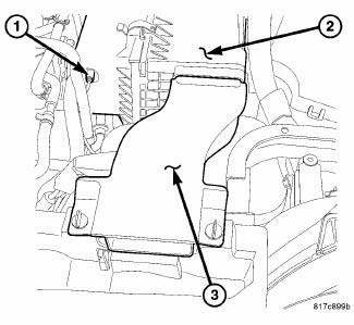
Fig. 30: Air Inlet Duct
1. Remove air inlet duct (3).
2. Disconnect negative battery cable.
3. Disconnect vacuum hose (1).
4. Remove air filter housing assembly (2).
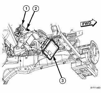
Fig. 31: Removing/Installing ECM - 2.0L Diesel
5. Disconnect both ECM (1) electrical connectors.
6. Remove ECM bracket retaining bolts (2) and remove ECM (3).
INSTALLATION

Fig. 32: Removing/Installing ECM - 2.0L Diesel
1. Install ECM (3) on mounting bracket. Torque fastener to 10.7N.m (95 lbs. in.).
2. Connect both ECM electrical connectors (1).

Fig. 33: Air Inlet Duct
3. Install air filter housing assembly (2).
4. Connect vacuum hose (1).
5. Connect negative battery cable.
6. Install air inlet tube (3).
7. Reprogram ECM.
 Description, Operation
DESCRIPTION
Fig. 29: Removing/Installing ECM - 2.0L Diesel
The ECM (3) is located in the left side of engine compartment attached to the
left inner fender below the air
filter housing.
OPERAT ...
 Module, final drive control
DESCRIPTION
The AWD ECM (electronic control module) mounts on the driver side cowl side
panel, where it is concealed by
the instrument panel. It communicates with other systems over the high-speed ...
See also:
Thermostat
Description
2.0L DIESEL/2.4L ENGINE
Fig. 115: THERMOSTAT
- AIR BLEED
- SEAL
- RETURN SPRING
- PELLET CHAMBER
The primary thermostat for the 2.0L diesel and 2.4L gas engines are locate ...
Pad, heater
DESCRIPTION
Vehicles equipped with the optional heated seat system have two carbon fiber
heated seat elements located in
each front seat. One heating element is used for each seat cushion and anot ...
VEHICLE IDENTIFICATION NUMBER
The Vehicle Identification Number (VIN) is on the left
front corner of the instrument panel and is visible from
outside of the vehicle through the windshield. This
number also appears on the Automo ...
