Dodge Journey: Installation
LEFT-HAND DRIVE
1. Clean any debris off the mating surfaces of the HCU and ABM.
CAUTION: When installing new O-rings or solenoid valve stem seals, do not use any type of lubricant.

Fig. 15: Solenoid Valve Seal
- - SEAL
- - SOLENOID VALVE STEM
2. If the seals (1) on the solenoid valve stems (2) are not new, replace them all. Each of the solenoid valve stem seals must be new to keep out moisture and debris;do not reuse solenoid valve stem seals.

Fig. 16: Internal Pump Connector O-Ring
- - O-RING
- - O-RING MOUNTING GROOVE
3. Replace the pump/motor connector O-ring (1) if it is not new. Be sure the O-ring is properly seated in the mounting groove (2).
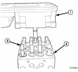
Fig. 17: Identifying ABM, HCU, & Solenoid Valve Stem
- - ABM
- - HCU
- - SOLENOID VALVE STEM
4. Align components and install the ABM (1) on the HCU (2).
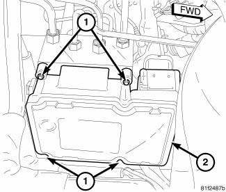
Fig. 18: ABM Mounting
5. Install the four screws (1) attaching the ABM (2) to the HCU. Tighten the mounting screws to 2 N.m (17 in. lbs.).

Fig. 19: Wiring Harness Connector At ABM
- - ABM (PART OF ICU)
- - WIRING HARNESS CONNECTOR
CAUTION: Before installing the ABM harness connector on the ABM, be sure the seal is properly installed in the connector.
6. Insert the ABM wiring harness connector (2) into the socket of the ABM (1) and close the cover, locking the connector in place.
7. Raise and support the vehicle.
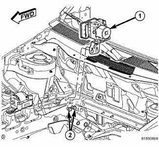
Fig. 20: Locating Integrated Control Unit (ICU)
8. Loosen the two mounting screws (2) as necessary and allow the ICU (1) mounting bracket to slide down over the mounting screws and hang the assembly in place. Tighten the two mounting screws (2) to 23 N.m (17 ft. lbs.).
9. Lower the vehicle.
10. Position the fresh air plenum and install the two mounting screws.
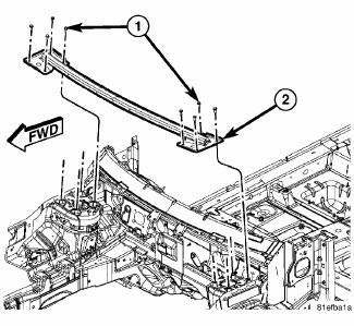
Fig. 21: Wheelhouse Brace
11. Install the wheelhouse brace (2). Install and tighten the eight mounting bolts (four each side) (1) to 48 N.m (35 ft. lbs.).
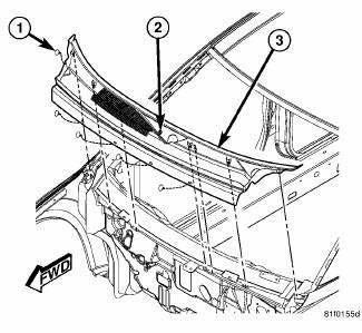
Fig. 22: Cowl Screen
12. Install the cowl screen. Install the push-pins (1) securing the cowl screen to the wheelhouse brace and cowl. Rotate the screw (2) in the center of the cowl screen 90º counterclockwise to lock the screen in place.
13. Install the wiper arms.
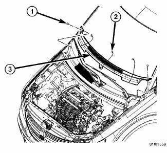
Fig. 23: Cowl Top Screen
14. Install the cowl top screen (3). Install the two push-pins (1) securing the cowl top screen at the ends.
Install the remaining push-pins (2).
15. Install the engine appearance cover.
16. Connect the negative cable on the battery negative post.
17. Hook up the scan tool to initialize the ABM and perform the following:
- Clear any faults.
- Perform the ABS Verification Test and road test the vehicle.
RIGHT-HAND DRIVE
1. Clean any debris off the mating surfaces of the HCU and ABM.
CAUTION: When installing new O-rings or solenoid valve stem seals, do not use any type of lubricant.
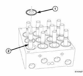
Fig. 24: Solenoid Valve Seal
- - SEAL
- - SOLENOID VALVE STEM
2. If the seals (1) on the solenoid valve stems (2) are not new, replace them all. Each of the solenoid valve stem seals must be new to keep out moisture and debris; do not reuse solenoid valve stem seals.
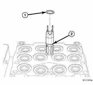
Fig. 25: Internal Pump Connector O-Ring
- - O-RING
- - O-RING MOUNTING GROOVE
3. Replace the pump/motor connector O-ring (1) if it is not new. Be sure the O-ring is properly seated in the mounting groove (2).

Fig. 26: ABM Assembly To HCU
- - ABM
- - HCU
- - SOLENOID VALVE STEM
4. Align components and install the ABM (1) on the HCU (2).
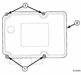
Fig. 27: ABM Mounting Screws
- - MOUNTING SCREWS
- - ABM
5. Install the four screws (1) attaching the ABM (2) to the HCU. Tighten the mounting screws to 2 N.m (17 in. lbs.).
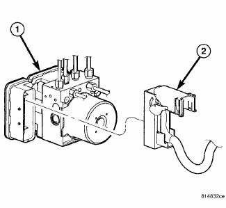
Fig. 28: Wiring Harness Connector At ABM
- - ABM (PART OF ICU)
- - WIRING HARNESS CONNECTOR
CAUTION: Before installing the ABM harness connector on the ABM, be sure the seal is properly installed in the connector.
6. Insert the ABM wiring harness connector (2) into the socket of the ABM (1) and close the cover, locking the connector in place.
7. Install the air inlet hose (1) between the air cleaner housing and engine.
8. Connect the negative cable on the battery negative post.
9. Hook up the scan tool to initialize the ABM and perform the following:
- Clear any faults.
- Perform the ABS Verification Test and road test the vehicle.
MODULE, DOOR
REMOVAL
1. Disconnect and isolate the battery negative cable.
2. Remove the door trim panel as necessary to gain access to the door control module.
3. Disconnect the electrical connectors.
4. Remove the door control module mounting fasteners and remove the module from the vehicle.
INSTALLATION
1. Place the door control module into position and install the mounting fasteners.
2. Connect the electrical connectors.
3. Install the door trim panel.
4. Install the battery negative cable.
 Removal
LEFT-HAND DRIVE
NOTE: The ABM is only separately serviceable for non-HSA (Hill Start
Assist) equipped
vehicles. Do not remove the ABM for vehicles equipped with HSA.
1. Disconnect the nega ...

See also:
Rocker arm, valve
DESCRIPTION
Fig. 133: Rocker Arm
- LASH ADJUSTER POCKET
- OIL SQUIRT HOLE
- ROLLER
The rocker arms are composed of steel stamping with an integral roller
bearing. The rocker arms incor ...
Description, Operation
DESCRIPTION
OPERATION
The following procedure has been established to assist technicians in the
field with enabling and running OBD
II Monitors. The order listed in the following procedur ...
Fluid
STANDARD PROCEDURE
FLUID LEVEL AND CONDITION CHECK
FLUID LEVEL CHECK
Fig. 351: Identifying Fluid Level Indicator
- FLUID LEVEL INDICATOR
NOTE: Only transmission fluid of the type labele ...
