Dodge Journey: Installation
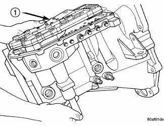
Fig. 474: Removing/Installing Valve Body
- - VALVE BODY
NOTE: If valve body assembly is being replaced or reconditioned, it is necessary to perform the PCM Quick Learn Procedure.
1. Install accumulators and springs as previously removed. Install valve body assembly to transaxle.
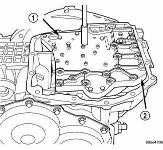
Fig. 475: Identifying Valve Body-To-Transaxle Case Bolts
- - VALVE BODY ATTACHING BOLTS (18)
- - VALVE BODY
2. Install and torque valve body-to-transaxle case bolts to 12 N.m (105 in. lbs.).
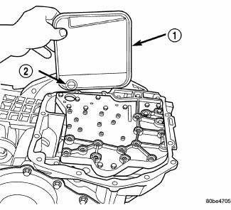
Fig. 476: Identifying Filter & O-Ring
- - OIL FILTER
- - O-RING
3. Install transaxle oil filter. Inspect the o-ring and replace if necessary.
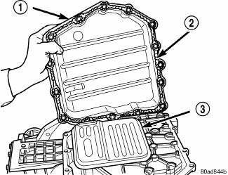
Fig. 477: Removing/Installing Oil Pan
- - OIL PAN
- - 1/8 INCH BEAD OF RTV SEALANT
- - OIL FILTER
4. Ensure the transaxle oil pan and transaxle case sealing surfaces are clean and dry. Install an 1/8" bead of MOPAR Silicone Rubber Adhesive Sealant to the oil pan and install.
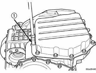
Fig. 478: Identifying Oil Pan Bolts
- - OIL PAN BOLTS (USE RTV UNDER BOLT HEADS)
5. Torque oil pan-to-transaxle case bolts to 19 N.m (165 in. lbs.).
6. Raise engine cradle crossmember into position.
7. Aligning index/scribe mark placed upon disassembly, Install four cradle-to-body bolts and torque to 162 N.m (120 ft. lbs.).
8. Lower vehicle.
9. Remove engine support fixture 8534B.
10. Raise vehicle.
11. Install and torque engine front and rear mount-to-cradle nuts to 54 N.m (40 ft. lbs.).
12. Lower vehicle.
13. Connect transmission range sensor connector.
14. Install manual valve lever to manual shaft.
15. Install gearshift cable to manual valve lever.
16. Install battery and tray.
17. Connect battery negative cable.
18. Fill transaxle with Mopar ATF +4 Transmission fluid.
 Assembly
NOTE: Cleanliness through entire disassembly and assembly of the valve
body cannot
be overemphasized. When disassembling, each part should be washed in a
suitable solvent, then dried by comp ...
See also:
Cooler, EGR
Description
Fig. 62: EGR COOLER
- EGR COOLER TO EGR VALVE TUBE
- MOUNTING SCREWS
- EGR COOLER MOUNTING SCREW
- MOUNTING SCREW
- EGR COOLER BODY
- EGR COOLER MOUNTING NUT
- EGR COOLE ...
Switch, backup lamp
DESCRIPTION
Fig. 43: Backup Lamp Switch
Vehicles equipped with a manual transmission (2) have a normally open,
spring-loaded plunger type backup
lamp switch (1). Vehicles with an optional elect ...
Diagnosis and Testing
LOWER BALL JOINT
1. Raise the vehicle allowing the front suspension to hang.
2. Remove the tire and wheel assembly.
3. Using Dial Indicator C-3339A, or equivalent, attach the dial indicator mou ...

