Dodge Journey: Installation
NOTE: LHD model shown in illustrations. RHD model similar.
RIGHT FRONT FLOOR DUCT

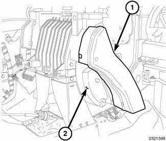
Fig. 71: Duct-Right Front Floor PM
NOTE: Illustration shown with instrument panel removed for clarity.
1. Connect the right floor duct (1) to the right side of the HVAC housing (2). Make sure the duct is fully engaged to the housing.
2. On LHD models, install the glove box bin.
LEFT FRONT FLOOR DUCT

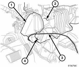
Fig. 72: Duct-Left Front Floor
NOTE: Illustration shown with instrument panel removed for clarity.
1. Connect the left floor duct (1) to the left side of the HVAC housing (2). Make sure the duct is fully engaged to the housing.
2. Install the screw (4) that secures the left floor duct to the HVAC housing. Tighten the screw to 2 N.m (17 in. lbs.)
3. On LHD models, connect the shift interlock cable (3) to the left floor duct.
4. On RHD models, install the glove box bin.
REAR FLOOR DISTRIBUTION DUCTS

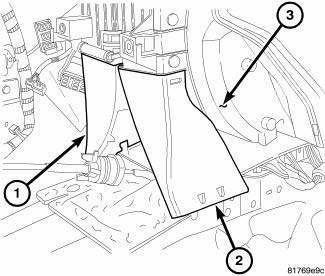
Fig. 73: Ducts-Rear Floor Distribution PM
1. Connect the left rear floor distribution duct (1) and the right rear floor distribution duct (2) as required to the HVAC housing (3). Make sure the ducts are fully engaged to the housing.
2. Install the rear seat floor ducts. 3. Install the instrument panel.
REAR SEAT FLOOR DUCTS

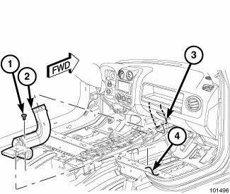
Fig. 74: Ducts-Rear Seat Floor PM
NOTE: Right side rear floor duct shown. Left side duct similar.
1. Connect the rear seat floor duct (2) to the rear floor distribution duct (3). Make sure the ducts are fully engaged to each other.
2. Engage the retainer that secures the rear seat floor duct to the floor support (4) and install the retaining screw (1). Tighten the screw to 2.2 N.m (20 in. lbs.).
3. Reinstall the carpet.
4. Install the front seat to the side of the vehicle being serviced.
5. Install the center floor console.
 Removal
WARNING: Disable the airbag system before attempting any steering
wheel, steering
column, or instrument panel component diagnosis or service. Disconnect
and isolate the battery negati ...
 Duct, instrument panel
Removal
WARNING: Disable the airbag system before attempting any steering
wheel, steering
column or instrument panel component diagnosis or service. Disconnect
and isolate the negati ...
See also:
MIRRORS
Inside Day/Night Mirror
A two-point pivot system allows for horizontal and
vertical mirror adjustment. Adjust the mirror to center on
the view through the rear window.
Headlight glare can be reduc ...
Valve, positive crankcase ventilation (PCV)
Description
The PCV valve contains a spring loaded plunger. The plunger meters the amount
of crankcase vapors routed
into the combustion chamber based on intake manifold vacuum.
Operation
Fig. ...
JUMP-STARTING
If your vehicle has a discharged battery it can be jumpstarted
using a set of jumper cables and a battery in
another vehicle or by using a portable battery booster
pack. Jump-starting can be danger ...
