Dodge Journey: Removal
BEVERAGE COOLER
WARNING: Disable the airbag system before attempting any steering wheel, steering column, or instrument panel component diagnosis or service. Disconnect and isolate the negative battery (ground) cable, then wait two minutes for the airbag system capacitor to discharge before performing further diagnosis or service. This is the only sure way to disable the airbag system. Failure to take the proper precautions may result in accidental airbag deployment and possible serious or fatal injury.
NOTE: LHD model shown in illustrations. RHD model similar.
OUTLET
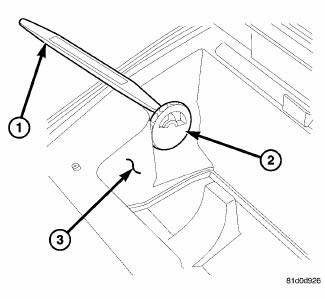
Fig. 143: Beverage Cooler Outlet
1. Using Trim Stick C-4755 or equivalent (1), disengage the three retaining tabs that secure the beverage cooler outlet (2) to side of the glove box bin (3).
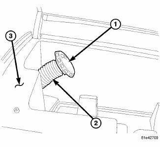
Fig. 144: Beverage Cooler Outlet & Hose
NOTE: If the beverage cooler cold air supply hose becomes disconnected from the air beverage cooler outlet and falls back into the instrument panel during outlet removal, the beverage cooler bin may need to be removed from the instrument panel for outlet installation.
2. Carefully pull the beverage cooler outlet (1) away from side of the beverage cooler bin (3) and disconnect the cold air supply hose (2) from the outlet. Make sure the end of the cold air supply hose remains in the bin and does not fall back into the instrument panel.
COLD AIR SUPPLY HOSE
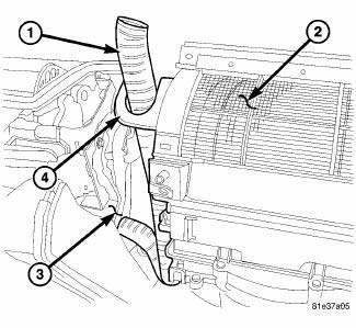
Fig. 145: Beverage Cooler Supply Hose
NOTE: Illustration shown with instrument panel removed for clarity.
1. Disconnect and isolate the negative battery cable.
2. Remove the instrument panel center bezel.
3. Remove the outer passenger side instrument panel air outlet.
4. Remove the beverage cooler outlet.
5. Remove the beverage cooler bin.
6. If equipped, remove the silencer trim panel out from underneath the passenger side of the instrument panel.
7. Remove the glove box bin.
8. Reach up underneath the instrument panel and disconnect the cold air supply hose (1) from the passenger side of the air distribution housing (3).
9. Working through the beverage cooler bin opening in the instrument panel, disengage the cold air supply hose from the bracket (4) located on the air inlet housing (2) and remove the hose. Note the routing of the hose and the instrument panel wiring for aid in reinstallation.
DEMISTER OUTLETS
WARNING: Disable the airbag system before attempting any steering wheel, steering column, or instrument panel component diagnosis or service. Disconnect and isolate the negative battery (ground) cable, then wait two minutes for the airbag system capacitor to discharge before performing further diagnosis or service. This is the only sure way to disable the airbag system. Failure to take the proper precautions may result in accidental airbag deployment and possible serious or fatal injury.
NOTE: Right side air outlet shown. Left side outlet similar.
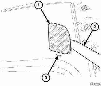
Fig. 146: Demister Outlet
1. Using Trim Stick C-4755 or equivalent (2), carefully disengage the three retaining tabs that secure each demister air outlet (1) to the instrument panel cover (3) and remove the outlet.
AIR OUTLETS
WARNING: Disable the airbag system before attempting any steering wheel, steering column, or instrument panel component diagnosis or service. Disconnect and isolate the negative battery (ground) cable, then wait two minutes for the airbag system capacitor to discharge before performing further diagnosis or service. This is the only sure way to disable the airbag system. Failure to take the proper precautions may result in accidental airbag deployment and possible serious or fatal injury.
OUTBOARD OUTLETS
NOTE: Right side air outlet shown. Left side outlet similar.
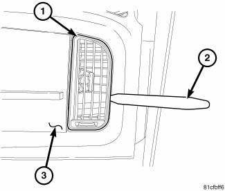
Fig. 147: Outboard Instrumental Panel Outlets
1. Using trim stick C-4755 or equivalent (2), carefully disengage the four retaining tabs (two tabs on each side) that secure each air outlet (1) to the instrument panel cover (3) and remove the outlet.
CENTER OUTLETS
NOTE: Take the proper precautions to protect the front face of the center bezel from cosmetic damage while performing this procedure.
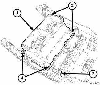
Fig. 148: Center Instrumental Panel Outlets
1. Remove the center bezel (3) from the instrument panel and place it on a workbench.
2. Remove the four screws (2 and 4) that secure the center instrument panel air outlets (1) to the center bezel and remove the outlets.
 Description
Fig. 142: Instrument Panel Outlets
There are two defroster air outlets (1) in the defroster grille (2) located
at the top of the instrument panel. The
airflow from the defroster outlets are dire ...
 Installation
BEVERAGE COOLER
NOTE: LHD model shown in illustrations. RHD model similar.
OUTLET
Fig. 149: Beverage Cooler Outlet & Hose
NOTE: If the beverage cooler cold air supply hose falls back ...
See also:
Link, stabilizer bar
REMOVAL
1. Raise and support the vehicle.
Fig. 60: TIRE AND WHEEL MOUNTING
2. Remove the wheel mounting nuts (3), then the tire and wheel assembly (1).
Fig. 61: Strut Mounting To Knuckle
3. W ...
REPLACEMENT PARTS
Use of genuine MOPAR parts for normal/scheduled
maintenance and repairs is highly recommended to ensure
the designed performance. Damage or failures
caused by the use of non-MOPAR parts for mainten ...
Diagnosis and Testing
BLOWER MOTOR
WARNING: Disable the airbag system before attempting any steering
wheel, steering
column, or instrument panel component diagnosis or service. Disconnect
and isolate the ...
