Dodge Journey: Operation, Removal
OPERATION
CAMSHAFT AND CRANKSHAFT SIGNALS
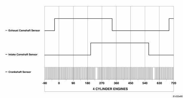
Fig. 29: 4 Cylinder Cam & Crank Signals
NOTE: The graphic represents the relationship between camshaft and crankshaft sensors edges with camshafts in "lock pin" position (cam shafts are not "phasing"). This is normally seen during idle.
Depiction of good camshaft and crankshaft square wave signals for 4 cylinder engines.
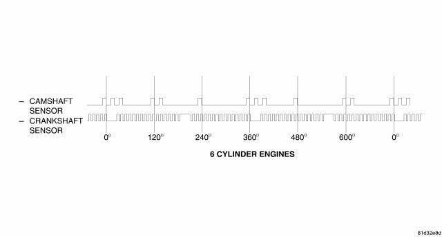
Fig. 30: 6 Cylinder Cam & Crank Signals
Depiction of good camshaft and crankshaft square wave signals for 6 cylinder engines.
REMOVAL
2.4L FRONT
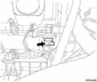
Fig. 31: Front Cam Sensor
1. Disconnect and isolate negative battery cable.
2. Disconnect electrical connector from camshaft position sensor.
3. Remove camshaft position sensor mounting screw.

Fig. 32: Removing/Installing Camshaft Position Sensor
4. Remove sensor.
2.4L REAR
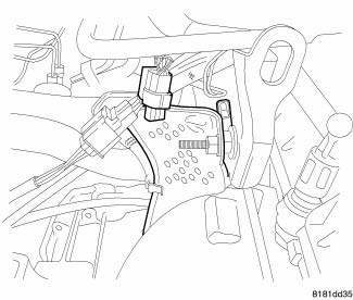
Fig. 33: Identifying Camshaft Position Sensor Heat Shield - Remove/Install
1. Disconnect and isolate negative battery cable.
2. Disconnect electrical connector at sensor.
3. Remove nut retaining heat shield.
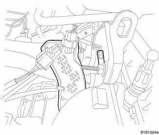
Fig. 34: Identifying Camshaft Position Sensor Heat Shield - Remove/Install
4. Pull heat shield out to uncover sensor.
5. Remove mounting bolt.
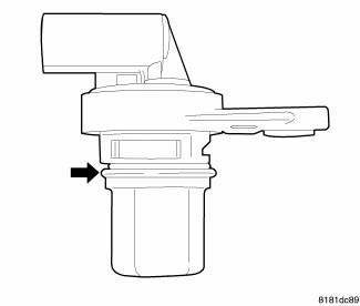
Fig. 35: Removing/Installing Camshaft Position Sensor
6. Remove sensor.
2.7L
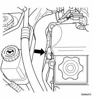
Fig. 36: Cam Sensor Location 2.7L
The camshaft position sensor is mounted in the front of the head.
1. Disconnect electrical connector from sensor.
2. Remove camshaft position sensor screw.
3. Without pulling on the connector, pull the sensor out of the chain case cover.
3.5L
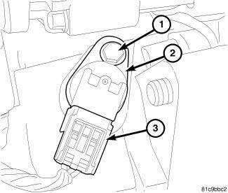
Fig. 37: 3.5L Camshaft Sensor
1. Disconnect and isolate the negative battery cable at battery.
2. Disconnect electrical connector (3) from camshaft position (CMP) sensor (2).
3. Remove bolt (1) and CMP sensor (2).

 Installation
2.4L FRONT
Fig. 38: Removing/Installing Camshaft Position Sensor
CAUTION: Install camshaft position (CMP) sensor utilizing twisting
motion. Make sure
CMP sensor is fully seated. Do n ...
See also:
JUMP-STARTING
If your vehicle has a discharged battery it can be jumpstarted
using a set of jumper cables and a battery in
another vehicle or by using a portable battery booster
pack. Jump-starting can be danger ...
Toe
Fig. 115: Steering Wheel Holding Tool
1. Center the steering wheel and lock it in place using a steering wheel
clamp.
NOTE: When setting toe, make sure to set rear toe to the preferred
spe ...
TIRE ROTATION RECOMMENDATIONS
Tires on the front and rear axles of vehicles operate at
different loads and perform different steering, driving,
and braking functions. For these reasons, they wear at
unequal rates.
These effect ...
