Dodge Journey: Tube, water inlet
Removal
WATER INLET TUBE

Fig. 126: WATER PUMP INLET TUBE WORLD ENGINE
- - NUTS
- - WATER PUMP INLET TUBE
- - WATER PUMP HOUSING
The water pump inlet tube (2) connects the water pump to the coolant adapter. This tube is sealed by an O-ring and held in place by fasteners to the water pump housing.
1. Drain cooling system.
2. Remove the coolant adapter and secondary thermostat.
3. Raise and support vehicle.
4. Remove inlet tube mounting nuts (1).
5. Remove inlet tube (2).
Installation
WATER INLET TUBE
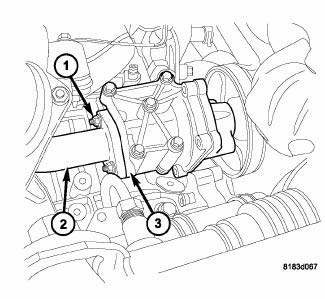
Fig. 127: WATER PUMP INLET TUBE WORLD ENGINE
- - NUTS
- - WATER PUMP INLET TUBE
- - WATER PUMP HOUSING
1. Inspect the O-ring for damage before installing the tube. Replace O-ring as necessary.
2. Lubricate O-rings with soapy water.
3. Install new water inlet gasket between tube and water pump housing (2).
4. Position water pump inlet tube (3) on water pump housing (2). Hand tighten nuts to aide in tube alignment.
5. Install secondary thermostat and coolant adapter. 6. Tighten coolant tube nuts (1) to 24 N.m (212 in. lbs.).
7. Fill cooling system.
 Thermostat
Description
2.0L DIESEL/2.4L ENGINE
Fig. 115: THERMOSTAT
- AIR BLEED
- SEAL
- RETURN SPRING
- PELLET CHAMBER
The primary thermostat for the 2.0L diesel and 2.4L gas engines are locate ...
 Transmission
COOLER, TRANSMISSION OIL
Description
Fig. 128: TRANSMISSION OIL COOLER
- Air Conditioning Condenser/Transmission Oil Cooler
- Transmission Cooler Outlet
- Transmission Cooler Inlet
- Air ...
See also:
Without intermediate shaft
NOTE: Never grasp the halfshaft assembly by the inner or outer boots
doing so may
damage to the boot.
NOTE: The inner tripod joints are designed with a retention feature that
prevents t ...
Switch, headlamp leveling, export
DESCRIPTION
Fig. 45: Identifying Park Assist Switch
The headlamp leveling switch (3) is used only on vehicles manufactured for
certain export markets where the
headlamp leveling system is requi ...
Removal
FOOT OPERATED PARKING BRAKE LEVER
1. Release the parking brake.
2. Raise and support the vehicle.
3. Manually release the parking brake cable tension.
4. Push the front cable strand into ...
