Dodge Journey: Cover, structural dust
Removal
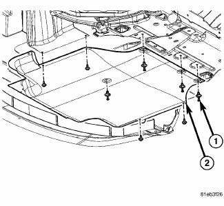
Fig. 172: Belly Pan
1. Raise and secure the vehicle on a hoist.
2. Remove the belly pan (2), if equipped.
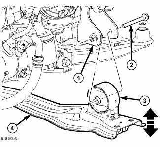
Fig. 173: Front Engine Mount Through Bolt
3. Remove the fore/aft crossmember (4).
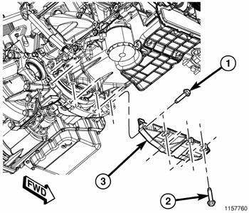
Fig. 174: Structural Collar
4. Remove three bolts (2) attaching the structural collar (3) to the oil pan.
5. Remove four bolts (1) and the structural collar (3) from the transmission.
Installation
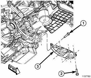
Fig. 175: Structural Collar
CAUTION: The collar must be tightened using this service procedure, as damage to transaxle case and/or oil pan may occur.
1. Position the structural collar (3) on the engine and transaxle.
2. Finger tighten all bolts (1) and (2).
NOTE: Make sure that structural collar (3) is flush with the oil pan and the transmission bell housing.
3. Install the vertical collar bolts (2) to the oil pan, pre-torque bolts to 1.1 N.m (10 in. lbs.).
4. Install the horizontal collar bolts (1) to the transmission and tighten to 55 N.m (40 ft. lbs.).
5. Starting with the center vertical bolts and working outward, final torque all bolts to 55 N.m (40 ft. lbs.).
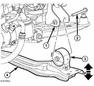
Fig. 176: Front Engine Mount Through Bolt
6. Install the fore/aft crossmember (4).
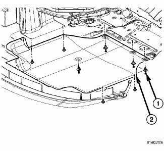
Fig. 177: Belly Pan
7. Install the belly pan (2), if equipped.
8. Lower the vehicle.
 Bearing(s), crankshaft, main
Standard Procedure
CRANKSHAFT MAIN BEARING FITTING
Fig. 169: Cylinder Block Main Bore Grade Marking
The grade marks for the cylinder block main bearing bore grade is located on
the pan rail jus ...
 Crankshaft
Description
The crankshaft is constructed of a forged micro alloy steel. The six throw,
nine counterweight crankshaft is
supported by four select fit main bearings with the number three serving as ...
See also:
Operation
Following are paragraphs that briefly describe the operation of each of the
major exterior lighting systems. The
lamps and the hard wired circuits between components related to the exterior
light ...
Standard procedure
ENGINE GASKET SURFACE PREPARATION
Fig. 4: PROPER TOOL USAGE FOR SURFACE PREPARATION
To ensure engine gasket sealing, proper surface preparation must be
performed, especially with the use of
alu ...
Removal
WARNING: Review safety precautions and warnings in this part
before performing
this procedure. See Heating and Air Conditioning/Plumbing - Warning
and. Failure to
follow the warnin ...
