Dodge Journey: Tray, battery
DESCRIPTION
The battery is placed and secured in a stamped steel battery tray. The battery tray is located in the left front side of the vehicle, just ahead of the left front wheel and tire assembly. The battery tray is secured to the left front frame rail with four bolts.
REMOVAL
WARNING: To protect the hands from battery acid, a suitable pair of heavy duty rubber gloves should be worn when removing or servicing a battery.
Safety glasses also should be worn.
WARNING: Remove metallic jewelry to avoid injury by accidental arcing of battery current.

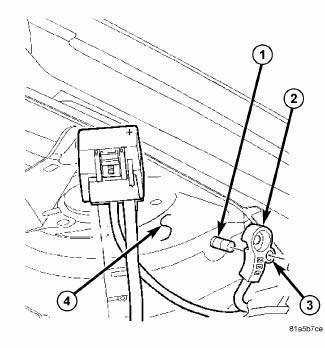
Fig. 44: Identifying Battery Cables & Terminals
CAUTION: The negative battery cable remote terminal (2) must be disconnected and isolated from the remote battery post (1) prior to service of the vehicle electrical systems. The negative battery cable remote terminal can be isolated by using the supplied isolation hole (3) in the terminal casing.
1. Disconnect and isolate the negative battery cable remote terminal from the remote battery post.
2. Remove the battery.

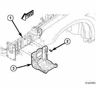
Fig. 45: View Of Battery Tray & Fasteners
3. Remove the four bolts (2) securing the battery tray (3) to the left front frame rail (1).
4. Remove the battery tray from the vehicle.
INSTALLATION
WARNING: To protect the hands from battery acid, a suitable pair of heavy duty rubber gloves should be worn when removing or servicing a battery.
Safety glasses also should be worn.
WARNING: Remove metallic jewelry to avoid injury by accidental arcing of battery current.
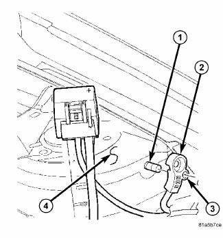
CAUTION: The negative battery cable remote terminal (2) must be disconnected and isolated from the remote battery post (1) prior to service of the vehicle electrical systems. The negative battery cable remote terminal can be isolated by using the supplied isolation hole (3) in the terminal casing.

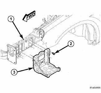
Fig. 46: View Of Battery Tray & Fasteners
1. Position the battery tray (3) onto the left front frame rail (1).
2. Install the bolts (2) securing the battery tray (3) to the frame rail (1).
Tighten the bolts to 16 N.m (142 in. lbs.)

Fig. 47: Identifying Battery Cables & Terminals
3. Install the battery.
4. Install the negative battery cable remote terminal onto the remote battery post.
Tighten the nut to 16.5 N.m (145 in. lbs.)
 Installation
BATTERY HARNESS
Fig. 36: Mounting Clips And TIPM Housing
1. Position the battery harness into the vehicle.
2. One at a time, install the battery harness retaining pushpins, fasteners and
rout ...
 Charging
...
See also:
FUSES
Totally Integrated Power Module
The Totally Integrated Power Module (TIPM) is located
in the engine compartment near the air cleaner assembly.
This center contains fuses and relays.
Totally Inte ...
Description
Fig. 1: BG6 Manual Transaxle
- OUTPUT SHAFT #2
- INPUT SHAFT
- OUTPUT SHAFT #1
- DIFFERENTIAL
The Aisin BG 6 6-speed transaxle is a constant-mesh transaxle that is
synchronized in all ...
FLUID CAPACITIES
FLUID CAPACITIES ...
