Dodge Journey: Speed Control
SWITCH, SPEED CONTROL
REMOVAL

Fig. 1: Removing/Installing Horn Switch
WARNING: Disconnect and isolate the battery negative (ground) cable before beginning steering wheel removal or installation. Allow the front airbag system capacitor to discharge for two minutes before removing the steering wheel or any front airbag system component. This will disable the front airbag system. Failure to disconnect the battery could result in accidental front airbag module deployment and possible personal injury.
Do not place a non-deployed airbag face down on a hard surface as the airbag will propel into the air if accidentally deployed, and could result in serious or fatal injury.
1. Disconnect and isolate the negative battery cable before beginning steering wheel removal. Allow the front airbag system capacitor to discharge for two minutes before removing the steering wheel or any front airbag system component.
2. Turn off ignition.
3. Remove the driver's side airbag.
4. Disconnect electrical connector (1) from horn switch (2).
5. Remove mounting screws (3) and horn switch (2) from steering wheel.
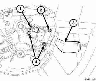
Fig. 2: Identifying Speed Control Switch Screws & Electrical Connector
6. Disconnect electrical connector (1) from speed control switch (3).
7. Remove screws (4) from speed control switch (3).
8. Remove speed control switch (3) from steering wheel.
INSTALLATION

Fig. 3: Identifying Speed Control Switch Screws & Electrical Connector
1. Install speed control switch (3) onto the locating pin (2) in the steering wheel.
2. Install speed control switch mounting screws (4) and tighten screws to 1.6 N.m (15 ins. lbs.).
3. Connect electrical connector (1) to speed control switch (3).
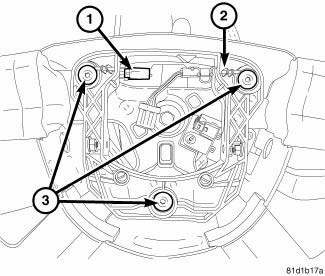
Fig. 4: Removing/Installing Horn Switch
4. Install horn switch (2) to steering wheel.
5. Install horn switch mounting screws (3) and tighten screws to 8 N.m (71 ins. lbs.).
6. Connect electrical connector to horn switch.
7. Install driver's side airbag.
8. Connect negative battery cable, tighten nut to 4.5 N.m (40 in. lbs.).
9. Verify vehicle and system operation.
 Wiring, trailer tow
DESCRIPTION
Fig. 73: Instruction Sheet Are Placed In Glove Box
Vehicles equipped with an optional Trailer Tow Preparation package have a
trailer tow wiring harness and an
instruction sheet (1) ...
 Brakes
...
See also:
Lamp, fog, front
REMOVAL
BULB
CAUTION: Do not contaminate the bulb glass by touching it with
your fingers or by
allowing it to contact other oily surfaces. Shortened bulb life will
result.
...
Adjustments
ADJUSTMENT - LATE PRODUCTION TYPE ONLY
Two unique brake lamp switches are used in this vehicle, depending upon
whether the vehicle was built during
early or late production. These switches are not ...
Description, Diagnosis and Testing
DESCRIPTION
Fig. 38: Front Hub And Bearing Mounting
The knuckle (3) is a single casting with legs machined for attachment to the
front strut assembly on the top and
steering linkage on the trai ...
