Dodge Journey: Description, Operation
DESCRIPTION
There are two unique park brake switches used on this vehicle, depending upon whether the vehicle has a foot-operated or hand-operated park brake lever mechanism.
FOOT-OPERATED
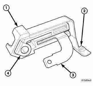
Fig. 52: Foot-Operated Park Brake Switch
The foot-operated park brake switch (1) is located on the park brake lever mechanism on the cowl side inner panel below the instrument panel, outboard of the steering column. This switch includes a spade-type output terminal (3) that connects the switch to the vehicle electrical system through a dedicated take out and connector of the body wire harness. The output terminal is integral to the stationary contact within a molded plastic insulator.
A locating tab on the insulator engages a slot in the park brake lever mechanism for positive switch location.
External to the insulator is a movable leaf contact with an integral grounding lug (4) on one end and an integral actuating lever and follower (2) on the opposite end. The switch is secured to and grounded by a single screw to the park brake lever mechanism.
The foot-operated park brake switch cannot be adjusted or repaired and, if ineffective or damaged, it must be replaced.
HAND-OPERATED
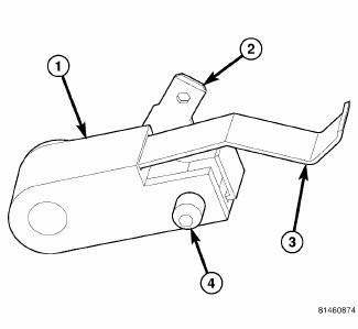
Fig. 53: Hand-Operated Park Brake Switch
The hand-operated park brake switch (1) is located on the park brake lever mechanism on the floor panel transmission tunnel below the center floor console. This switch includes a spade-type output terminal (2) that connects the switch to the vehicle electrical system through a dedicated take out and connector of the body wire harness. The output terminal is integral to the stationary contact within a molded plastic insulator.
A locating tab (4) on the insulator engages a slot in the park brake lever mechanism for positive switch location.
External to the insulator is a movable leaf contact (3) with an integral grounding lug on one end and an integral actuating lever and follower on the opposite end. The switch is secured to and grounded by a single screw to the park brake lever mechanism.
The hand-operated park brake switch cannot be adjusted or repaired and, if ineffective or damaged, it must be replaced.
OPERATION
Both the foot-operated and hand-operated park brake switch are normally closed, mechanically actuated leaf contact switches that are operated by the foot or hand park brake lever mechanism. The switch is grounded through its mounting to the park brake lever mechanism and provides a ground input to the ElectroMechanical Instrument Cluster (EMIC) (also known as the Cab Compartment Node/CCN) on a park brake switch sense circuit whenever the park brake is applied, and opens this circuit whenever the park brake is released. The park brake switch sense input to the EMIC is used as a logic input by the EMIC for control of the brake indicator and may also be used as a logic input for other electronic features in the vehicle.
The park brake switch as well as the hard wired inputs and outputs of the switch may be diagnosed using conventional diagnostic tools and procedures. However, conventional diagnostic methods will not prove conclusive in the diagnosis of the electronic controls and communication between other modules and devices that rely upon inputs from the park brake switch. The most reliable, efficient, and accurate means to diagnose the electronic controls and communication related to park brake switch operation requires the use of a diagnostic scan tool. Refer to the appropriate diagnostic information.

 Diagnosis and Testing
PARK BRAKE SWITCH
WARNING: To avoid serious or fatal injury on vehicles equipped
with airbags, disable
the Supplemental Restraint System (SRS) before attempting any steering
wheel, s ...
See also:
Diagnosis and Testing
BATTERY SYSTEM
The battery, starting, and charging systems in the vehicle operate with one
another and must be tested as a
complete system. In order for the engine to start and the battery to main ...
Cleaning, Inspection
CLEANING
Drain cooling system and refill with clean water. Refer to drain and fill
procedures in this service information .
Run engine with radiator cap installed until upper radiator hose is ho ...
Accumulator
DESCRIPTION
Fig. 238: Identifying Underdrive & Overdrive Accumulators
- RETURN SPRING
- UNDERDRIVE CLUTCH ACCUMULATOR
- SEAL RING (2)
- OVERDRIVE CLUTCH ACCUMULATOR
The 41TE underd ...
