Dodge Journey: Removal
BULB
Each rear lamp unit for this vehicle consists of two pieces. An outer rear lamp unit that is secured at the rear of each quarter panel includes bulbs for the park (or tail) lamps, the brake (or stop) lamps and the turn signal lamps. An inner rear lamp is secured on each outboard side of the liftgate outer panel adjacent to the outer lamp and also includes a bulb for the park (or tail) lamps as well as a bulb for the backup (or reverse) lamps.
OUTER LAMP
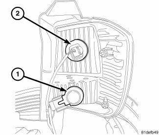
Fig. 24: Tail/Stop/Rear Side Marker And Turn Signal
NOTE: The outer rear lamp unit contains two bulbs. They are the tail/stop/rear side marker (1) and the turn signal (2). The service procedures for each bulb are the same, only the bulb sizes and types may differ.
1. Disconnect and isolate battery negative cable.
2. Remove the outer rear lamp unit.
3. Firmly grasp the appropriate bulb socket (1 or 2 ) on the back of the lamp housing and rotate it counterclockwise about 30 degrees to unlock it.
4. Pull the socket and bulb straight out of the lamp.
5. Pull the base of the bulb straight out of the socket.
INNER LAMP
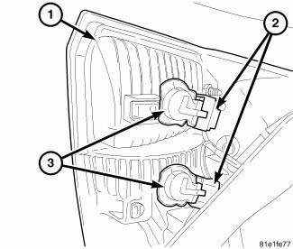
Fig. 25: Bulb Socket On Back Of Lamp Housing
NOTE: The inner rear lamp unit contains two bulbs. The upper socket contains the tail lamp bulb, while the lower socket contains the backup lamp bulb. The service procedures for each bulb are the same, only the bulb sizes and types may differ.
1. Disconnect and isolate the battery negative cable.
2. Remove the inner rear lamp unit. 3. Firmly grasp the appropriate bulb socket (3) on the back of the lamp housing and rotate it counterclockwise about 30 degrees to unlock it.
4. Pull the socket and bulb straight out of the lamp.
5. Pull the base of the bulb straight out of the socket.
LAMP
Each rear lamp unit for this vehicle consists of two pieces. An outer rear lamp unit that is secured at the rear of each quarter panel includes bulbs for the park (or tail) lamps, the brake (or stop) lamps and the turn signal lamps. An inner rear lamp is secured on each outboard side of the liftgate outer panel adjacent to the outer lamp and also includes a bulb for the park (or tail) lamps as well as a bulb for the backup (or reverse) lamps. These lamp units are serviced individually as follows.
OUTER
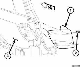
Fig. 26: Outer Rear Lamp Unit
1. Disconnect and isolate battery negative cable.
2. Open the liftgate to access and remove the two push pin fasteners (2) that secure the inboard side of the outer rear lamp unit (1) to the side jamb of the liftgate opening.
3. Pull the outboard side of the outer rear lamp unit rearward far enough to disengage the two locating pins on the back of the lamp housing from the plastic grommets in the lamp opening of the body sheet metal (3).
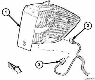
Fig. 27: Body Wire Harness Connectors
4. Pull the lamp (1) away from the vehicle far enough to access and disconnect the two body wire harness connectors (2 and 3) from the bulb socket connector receptacles on the back of the lamp housing.
5. Remove the lamp from the vehicle.
INNER
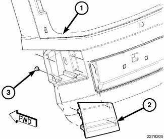
Fig. 28: Inner Rear Lamp Unit
1. Disconnect and isolate the battery negative cable.
2. Open the liftgate (1) to access and remove the two screws (3) that secure the outboard side of the inner rear lamp unit (2) to the liftgate lamp opening.
3. Pull the inboard side of the inner rear lamp unit rearward far enough to disengage the two locating pins on the back of the lamp housing from the plastic grommets in the liftgate lamp opening.
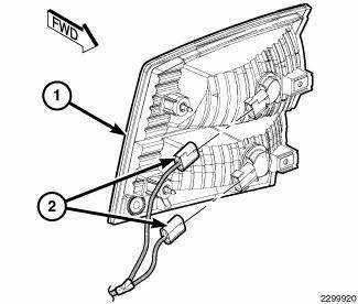
Fig. 29: Liftgate Wire Harness Connectors
4. Pull the lamp (1) away from the vehicle far enough to access and disconnect the two liftgate wire harness connectors (2) from the bulb socket connector receptacles on the back of the lamp housing.
5. Remove the lamp from the vehicle.
 Installation
BULB
Each rear lamp unit for this vehicle consists of two pieces. An outer rear
lamp unit that is secured at the rear of
each quarter panel includes bulbs for the park (or tail) lamps, the brake ( ...
See also:
Adjustments
ADJUSTMENT
The right and left support assemblies are slotted to allow for right/left
drive train adjustment in relation to drive
shaft assembly length.
Check and reposition right and left engin ...
Diagnosis and Testing
ELECTRIC BACKLIGHT (EBL) SYSTEM
NOTE: Illumination of the defogger switch indicator lamp does not
necessarily mean
that electrical current is reaching the rear window glass and/or the outside ...
Removal, Installation
REMOVAL
WARNING: Disable the airbag system before attempting any steering
wheel, steering
column, or instrument panel component diagnosis or service. Disconnect
and isolate the negat ...

