Dodge Journey: Standard procedure
FRONT LAMP AIMING
VEHICLE PREPARATION FOR LAMP ALIGNMENT
1. Check for and correct any burnt out bulbs.
2. If the vehicle is equipped with headlamp leveling, be certain that the headlamp leveling switch is in the 0 (zero) position.
3. Repair or replace any ineffective, worn or damaged body or suspension components that could hinder proper lamp alignment.
4. Verify proper tire inflation pressures.
5. Remove any accumulations of mud, snow or ice from the vehicle underbody and clean the front lamp lenses.
6. Verify that there is no load in the vehicle (cargo or passengers), except for the driver.
7. The fuel tank should be FULL. Add 2.94 kilograms (6.5 pounds) of weight over the fuel tank for each estimated gallon of missing fuel.
8. Verify correct vehicle suspension height.
LAMP ALIGNMENT SCREEN PREPARATION
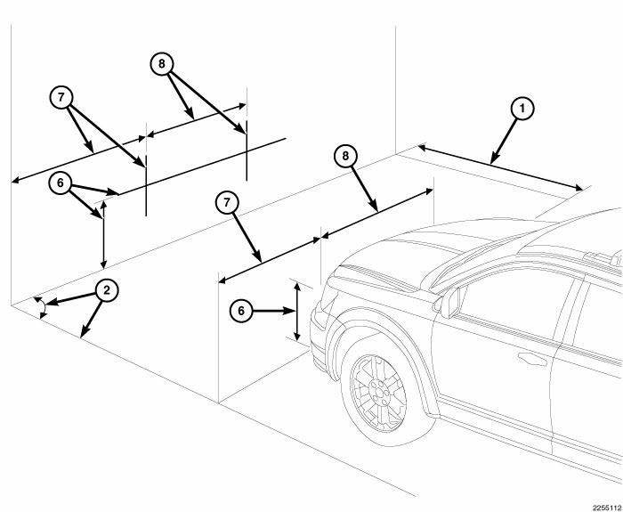
Fig. 2: Lamp Alignment Screen Preparation
The procedure that follows will prepare a suitable front lamp alignment screen.
1. Tape a line on a level floor 7.62 meters (25 feet) away from and parallel to the flat wall that will be used as the lamp alignment screen. The level floor will be used as the horizontal zero reference.
2. An adjacent wall or floor member that is perpendicular to the alignment screen can be used as the vertical zero reference. If there is no adjacent wall or floor member that is perpendicular to the screen, tape a second line on the floor perpendicular to both the alignment screen and the first line, and outboard of either side of where the vehicle will be positioned. This will be used as the vertical zero reference.
3. Position the vehicle so that the side of the vehicle is parallel to the vertical zero reference, and so that the front of the lamp lenses are in the vertical plane of the parallel line taped on the floor 7.62 meters (25 feet) away from the screen.
4. Rock the vehicle side-to-side three times to allow the suspension to stabilize.
5. Jounce the front suspension three times by pushing downward on the front bumper and releasing.
6. Measure the distance between the optical center of one of the lamps being aimed (head or fog) and the floor (horizontal zero reference). Transfer this measurement to the alignment screen with a piece of tape placed horizontally to the floor. This line will be used as the lamp horizontal reference.
7. Measure the distance between the vertical zero reference and the optical center of the nearest lamp being aimed (head or fog). Transfer this measurement to the alignment screen with a piece of tape placed vertically across the appropriate lamp (head or fog) horizontal reference. This is the centerline reference for the first lamp.
8. Measure the distance on center between the first and the second lamp being aimed. Transfer this measurement to the alignment screen with a second piece of tape placed vertically across the appropriate lamp (head or fog) horizontal reference. This is the centerline reference for the second lamp.
HEADLAMP ALIGNMENT
NOTE: Due to the linear nature of the headlamp cutoff, a properly aimed low beam headlamp will project the top edge of the high intensity pattern on the alignment screen just below the horizontal line to 50 millimeters (2 inches) below the horizontal line for domestic market vehicles, or to 130 millimeters (5.12 inches) below the horizontal line for export market vehicles. No horizontal (right/left) adjustment is required for this headlamp beam pattern in domestic market vehicles. Export market vehicles have a second horizontal (right/left) adjustment screw provided on the outboard side of the headlamp unit rear housing. The high beam pattern will be correct when the low beams are properly aimed.
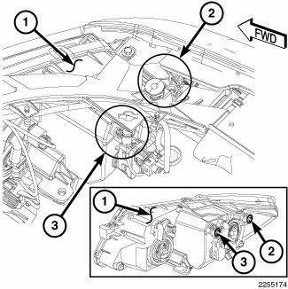
Fig. 3: Headlamp Alignment
1. Turn the headlamps ON and select the LOW beams.
2. Rotate the vertical adjustment screw (3) on each front lamp unit (1) to adjust the beam height as required.
3. For export markets only, rotate the horizontal adjustment screw (2) on each lamp to adjust the beam right or left as required.
FOG LAMP ALIGNMENT
NOTE: A properly aimed front fog lamp will project a pattern on the alignment screen 100 millimeters (4 inches) below the fog lamp centerline and straight ahead of the lamp for domestic market vehicles. On export market vehicles, a properly aimed fog lamp will project a pattern on the alignment screen 200 millimeters (8 inches) below the fog lamp centerline and straight ahead of the lamp.
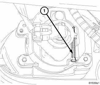
Fig. 4: Fog Lamp Alignment
1. Turn the fog lamps ON.
2. Raise the lower portion of the inner wheel house shield to gain access to the rear of the fog lamp unit.
3. Rotate the vertical adjustment screw (1) on each lamp to adjust the beam height as required.
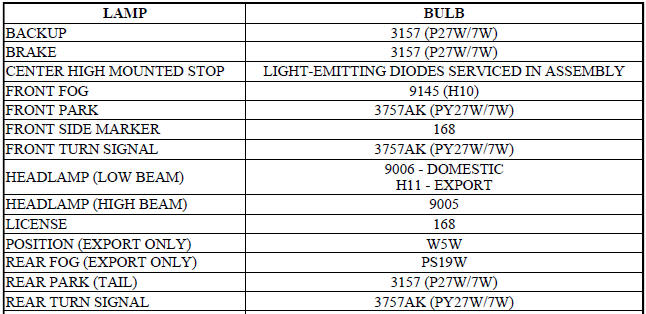
SPECIFICATIONS
BULB APPLICATION TABLE

 Diagnosis and Testing
LAMPS/LIGHTING - EXTERIOR
WARNING: To avoid serious or fatal injury on vehicles equipped
with airbags, disable
the Supplemental Restraint System (SRS) before attempting any steering
...
 Cam, turn signal cancel
DESCRIPTION
The turn signal cancel cam is concealed within the clockspring case on the
steering column. The turn signal
cancel cam consists of integral eccentrics on the outer circumference of the ...
See also:
Removal, Installation
REMOVAL
WARNING: Refer to the applicable warnings and cautions for this
system before
performing the following operation. Failure to follow the warnings and
cautions may result in po ...
Pod, switch
DESCRIPTION
Fig. 10: Accessory Switch Bank Module
The Accessory Switch Bank Module (ASBM) is located in the center stack area
of the instrument panel just
below the heater and air conditioner d ...
SUGGESTIONS FOR OBTAINING SERVICE FOR YOUR VEHICLE
Prepare For The Appointment
If you’re having warranty work done, be sure to have the
right papers with you. Take your warranty folder. All
work to be performed may not be covered by the
warranty ...
