Dodge Journey: Disassembly
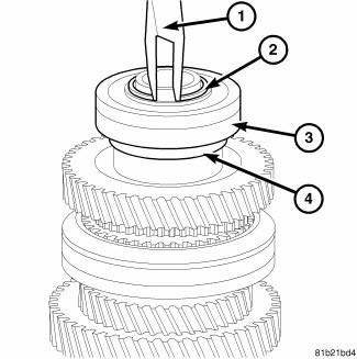
Fig. 200: Snap Ring At Output Shaft Case Bearing
1. Remove the snap ring (2) from the output shaft.
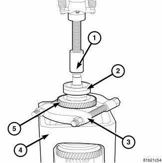
Fig. 201: Output Shaft Case Bearing And Gear
2. Use Bearing Splitter P-334 (3), Cage 8925-3 (4) and a press (1) to remove bearing (2) and third gear (5) from output shaft.
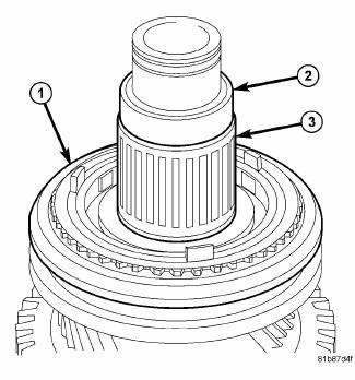
Fig. 202: Input Spacer & Bearing
3. Remove the spacer (2), ball, needle roller bearing (3) and synchronizer ring set (1).
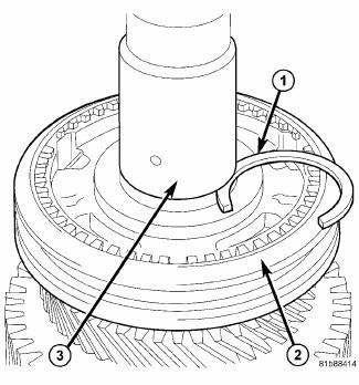
Fig. 203: Input Upper Snap Ring
4. Remove the shaft snap ring (1).
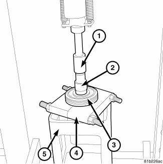
Fig. 204: Third/Fourth Gear Synchronizer & Output Shaft
5. Use Press Plate 9647 (4) and Cage 8925-3 (5) to remove third/forth gear synchronizer (3) from output shaft (2).
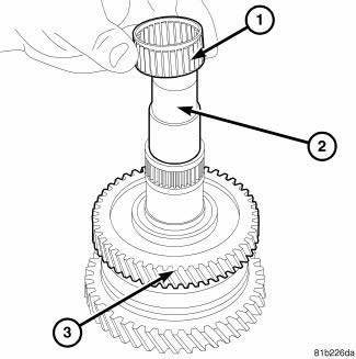
Fig. 205: Bearing & Output Shaft
6. Remove the bearing (1) from the output shaft (2).
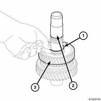
Fig. 206: Snap Ring From Output Shaft
7. Remove the spacer and snap ring (1) from output shaft (2).
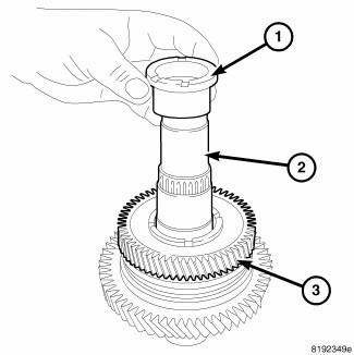
Fig. 207: Output Shaft Spacer
8. Remove the second gear inner race (1) from the output shaft (2).
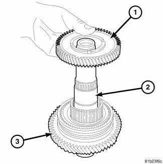
Fig. 208: Output Shaft 2nd Gear
9. Remove second gear (1) from output shaft (2).
10. Remove the needle bearing.
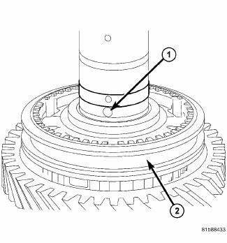
Fig. 209: Ball
11. Remove the ball (1).
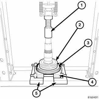
Fig. 210: First/Second Gear Synchronizer & First Gear
12. Use Bearing Splitter P-334 (4) press off the first/second gear synchronizer (3) and first gear (3).
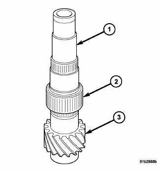
Fig. 211: First Gear Needle Bearing & Output Shaft
13. Remove the Needle bearing (2) from the output shaft (1).
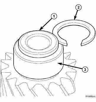
Fig. 212: Input Lower Snap Ring
14. Remove the shaft snap ring (2).
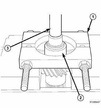
Fig. 213: Cylindrical Roller Bearing
15. Remove the cylindrical roller bearing (2) using Bearing Splitter 1130 (1) and a Press.

 Assembly
Fig. 214: First Gear Needle Bearing & Output Shaft
NOTE: Use ATF on all parts that are to be assembled in this procedure.
1. Install the first and first gear needle bearing (2) on the out ...
See also:
Description, Operation
DESCRIPTION
There are two unique park brake switches used on this vehicle, depending upon
whether the vehicle has a foot-operated or hand-operated park brake lever
mechanism.
FOOT-OPERATED
Fi ...
Switch, backup lamp
DESCRIPTION
Fig. 43: Backup Lamp Switch
Vehicles equipped with a manual transmission (2) have a normally open,
spring-loaded plunger type backup
lamp switch (1). Vehicles with an optional elect ...
IF YOU NEED ASSISTANCE
The manufacturer and its authorized dealers are vitally
interested in your satisfaction. We want you to be happy
with our products and services.
Warranty service must be done by an authorized deale ...
