Dodge Journey: Description
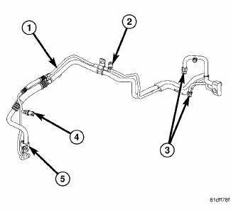
Fig. 246: Liquid/Suction Line Assembly with Rear A/C
NOTE: A/C liquid and suction line assembly with rear A/C shown. Front A/C only line assembly similar.
The A/C liquid line is serviced in two sections. The front section of the A/C liquid line is the refrigerant line that carries liquid refrigerant from the A/C condenser to the A/C receiver/drier and is only serviced as an assembly with receiver/drier. The rear section of the A/C liquid line (1) carries liquid refrigerant from the A/C receiver/drier to the A/C expansion valve and includes the high side service port (2) and a fitting for the A/C pressure transducer (4). The rear section of the A/C liquid line is only serviced as an assembly with the A/C suction line (5). When equipped with rear A/C, the A/C liquid and suction line assembly includes connections for the underbody refrigerant lines (3).
NOTE: Replacement of the refrigerant line O-ring seals and gaskets is required anytime a refrigerant line is disconnected. Failure to replace the rubber O-ring seals and metal gaskets could result in a refrigerant system leak.
The A/C liquid and suction line assembly has no serviceable parts except for the metal gaskets, rubber O-ring seals and the service port valve cores. The O-ring seals used on the connections are made from a special type of rubber not affected by R-134a refrigerant. The O-ring seals and gaskets must be replaced whenever the A/C liquid/suction line assembly is disconnected.
The A/C liquid and suction line assembly cannot be repaired and must be replaced if leaking or damaged.
 Line, A/C liquid
...
 Removal
WARNING: Review safety precautions and warnings in this part
before performing
this procedure. See Heating and Air Conditioning/Plumbing - Warning
and. Failure to
follow the warnin ...
See also:
Description, Operation, Diagnosis and Testing
DESCRIPTION
Fig. 1: Accessory Switch Bank Module
Vehicles with the heated seat option can be visually identified by the two
heated seat switches (1) located in the
center stack of the instrumen ...
Tube, water inlet
Removal
WATER INLET TUBE
Fig. 126: WATER PUMP INLET TUBE WORLD ENGINE
- NUTS
- WATER PUMP INLET TUBE
- WATER PUMP HOUSING
The water pump inlet tube (2) connects the water pump to the co ...
Assembly
Fig. 239: Output Shaft #2 & Needle Bearing
1. Install the reverse needle bearing (1) onto the output shaft # 2 (2).
Fig. 240: Synchronizer
NOTE: Pay attention to the direction when inser ...
