Dodge Journey: Description, Operation
DESCRIPTION
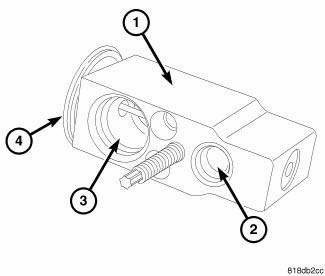
Fig. 265: A/C Expansion Valve Description KA
The A/C expansion valve controls the amount of refrigerant entering the A/C evaporator. The A/C expansion valve is of a thermostatic expansion valve (TXV) design and consists of an aluminum H-valve type body (1) with an inlet port (2), outlet port (3) and an integral thermal sensor (4).
The A/C expansion valve is located in the engine compartment at the dash panel, between the A/C refrigerant lines and the A/C evaporator.
OPERATION
The A/C expansion valve controls the high-pressure, low temperature liquid refrigerant from the A/C liquid line and converts it into a low-pressure, low-temperature mixture of liquid and gas before it enters the A/C evaporator. A mechanical sensor in the A/C expansion valve monitors the temperature and pressure of the refrigerant leaving the A/C evaporator through the A/C suction line, and adjusts the orifice size at the liquid line port to let the proper amount of refrigerant into the evaporator to meet the vehicle A/C cooling requirements.
Controlling the refrigerant flow through the A/C evaporator ensures that none of the refrigerant leaving the A/C evaporator is still in a liquid state, which could damage the A/C compressor.
NOTE: Replacement of the refrigerant line O-ring seals is required anytime a refrigerant line is disconnected from the expansion valve, or if the expansion valve is removed. Failure to replace the rubber O-ring seals may result in a refrigerant system leak.
The A/C expansion valve is factory calibrated and cannot be adjusted or repaired and must be replaced if inoperative or damaged.

 Diagnosis and Testing
A/C EXPANSION VALVE
WARNING: Refer to the applicable warnings and cautions for this
system before
performing the following operation. Failure to follow the warnings and
cautions may ...
See also:
Diagnosis and Testing
BRAKE LAMP SWITCH
WARNING: To avoid serious or fatal injury on vehicles equipped
with airbags, disable
the Supplemental Restraint System (SRS) before attempting any steering
wheel, s ...
Unit, heater
DESCRIPTION
Fig. 323: Positive Temperature Coefficient Heater - Description
NOTE: LHD model shown. RHD model similar.
An electric positive temperature coefficient (PTC) heater unit (1) is us ...
Switch, hazard warning
DESCRIPTION
Fig. 44: Instrument Panel Switch Pod
The hazard switch (3) is integral to the instrument panel switch pod (1),
which is secured to the instrument
panel center bezel just above the h ...
