Dodge Journey: Description, Operation
DESCRIPTION
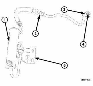
Fig. 231: Receiver/Drier Description
The A/C receiver/drier (1) stores unused refrigerant, filters the refrigerant, helps remove moisture from the refrigerant and retains any refrigerant vapor that may leave the A/C condenser until it becomes a liquid.
The A/C receiver/drier is installed on the high-side of the A/C system, below the engine compartment behind the right side of the front fascia and is connected to the right side of the A/C condenser by an integral refrigerant line (2). An integral mounting bracket (5) secures the A/C receiver/drier to the right front frame rail and the connections are sealed by use of rubber O-ring seals (3) and metal gaskets (4).
OPERATION
The A/C receiver/drier performs a filtering action to prevent foreign material in the refrigerant from contaminating the A/C expansion valve. Refrigerant enters the A/C receiver/drier as a high-pressure, low temperature liquid. Desiccant inside the A/C receiver/drier absorbs any moisture which may have entered and become trapped within the refrigerant system. In addition, during periods of high demand operation of the A/C system, the A/C receiver/drier acts as a reservoir to store surplus refrigerant.
NOTE: Replacement of the refrigerant line O-ring seals and gaskets is required anytime a refrigerant line is disconnected. Failure to replace the rubber O-ring seals and metal gaskets could result in a refrigerant system leak.
The A/C receiver/drier has no serviceable parts except for the O-ring seals and gaskets. The O-ring seals used on the connections are made from a special type of rubber not affected by R-134a refrigerant. The O-ring seals and gaskets must be replaced whenever the A/C receiver/drier is disconnected.
The A/C receiver/drier cannot be repaired and must be replaced if leaking or damaged, or if an internal failure of the A/C compressor has occurred.

 Removal
WARNING: Review safety precautions and warnings in this part
before performing
this procedure. Failure to
follow the warnings and cautions could result in possible serious or
fata ...
See also:
Description - monitored component
There are several components that will affect vehicle emissions if they
malfunction. If one of these components
malfunctions the Malfunction Indicator Lamp (Check Engine) will illuminate.
Some o ...
Standard procedure, Removal
STANDARD PROCEDURE
FRONT LAMP UNIT MOISTURE CLEARING
Some occasional moisture accumulation inside a vented front lamp unit is
normal and appears as a fogging on
the inside of the lamp lens, simil ...
Description
A manual temperature control (MTC) single zone heating-A/C system, automatic
temperature controlled (ATC)
dual zone heating-A/C system, MTC tri-zone heating-A/C system and an ATC
tri-zone heating ...
