
Dodge Journey: Module, glow plug
DESCRIPTION
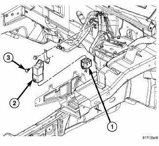
Fig. 23: Locating Diesel Glow Plug Control Module
The glow plug control module is mounted to the fuel filter/water separator bracket, and is controlled by the engine control module.
OPERATION
When the ignition (key) switch is placed in the ON position, a signal is sent to the ECM relating current engine coolant temperature. This signal is sent from the engine coolant temperature sensor.
The glow plug control module receives information about the glow function from the engine control module.
The start of glow plug operation, the period of glow plug operation, the actuation frequency and the pulse duty factor are therefore determined by the engine control module.
REMOVAL
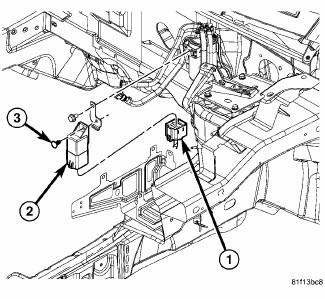
Fig. 24: Locating Diesel Glow Plug Control Module
1. Disconnect the glow plug module harness connector (1)
2. Remove the fastener (3).
3. Remove the glow plug module (2).
INSTALLATION
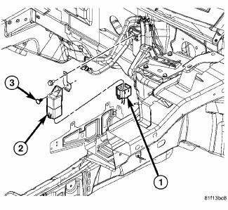
Fig. 25: Locating Diesel Glow Plug Control Module
1. Install the glow plug module (2).
2. Install the fastener (3).
3. Reconnect the glow plug module harness connector (1)
 Installation
2.4L
Fig. 17: Removing/Installing Ignition Coil
1. Install ignition coil onto spark plug.
Fig. 18: Removing/Installing Ignition Coil Mounting Bolts
2. Install ignition coil mounting bolt, tigh ...
 Plug, glow
DESCRIPTION
Fig. 26: Glow Plug
Glow plugs are used to help start a cold or cool engine. The glow plugs will
heat up and glow to heat the
combustion chamber of each cylinder. An individual glow ...
See also:
Sensor, transmission range
DESCRIPTION
Fig. 386: Locating Transmission Range Sensor (TRS)
- TRANSMISSION RANGE SENSOR
The Transmission Range Sensor (TRS) (1) is mounted to the top of the valve
body inside the transa ...
Description, Operation, Specifications
DESCRIPTION
NOTE: All engines use a fixed ignition timing system. Basic ignition
timing is not
adjustable. All spark advance is determined by the Powertrain Control Module
(PCM).
The ign ...
Cover(s), cylinder head, left
REMOVAL
1. Disconnect negative battery cable.
2. Disconnect electrical connectors from ignition coils and capacitor.
Reposition electrical harness.
3. Remove ground strap from cylinder head c ...
