Dodge Journey: Valve, one way check
Description
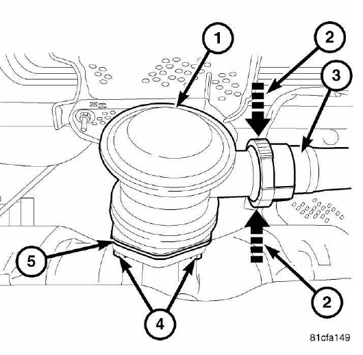
Fig. 16: AIR INJECTION CHECK VALVE
The air injection check valve (1) is a one-valve check valve that allows air to flow in one direction only. The valve is located at exhaust side of the engine at the top of the exhaust manifold.
Operation
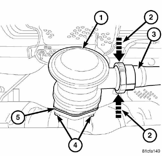
Fig. 17: AIR INJECTION CHECK VALVE
The air injection check valve (1) allows air pumped from the air injection pump to enter the exhaust manifold during cold engine starts only. Air pressure from the air injection pump causes the spring inside the air injection check valve to open allowing air to flow into the exhaust system.
Removal
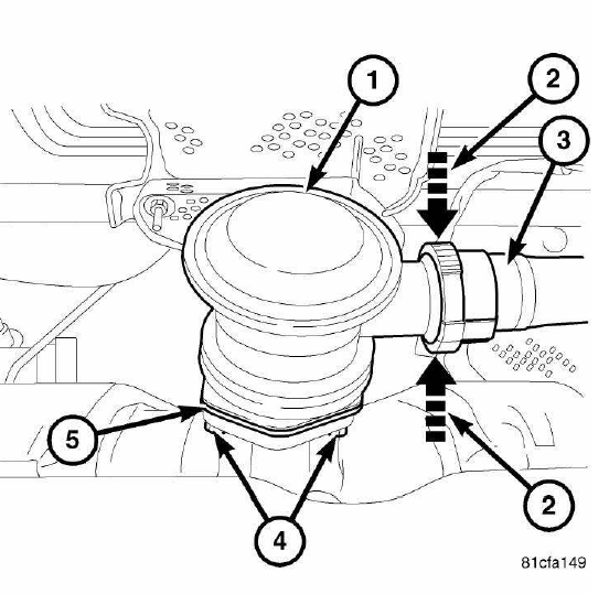
Fig. 18: AIR INJECTION CHECK VALVE
WARNING: THE EXHAUST MANIFOLD, AIR INJECTION PIPES, EXHAUST PIPES AND CATALYTIC CONVERTER(S) BECOME VERY HOT DURING ENGINE OPERATION. ALLOW ENGINE TO COOL BEFORE REMOVING AIR INJECTION CHECK VALVE. FAILURE TO ALLOW ENGINE TO COOL BEFORE REMOVAL MAY RESULT IN PERSONAL INJURY CAUSED BY BURNS.
1. Remove engine cover.
2. Remove air outlet tube (3) by pushing the ends (2) together, while pulling the air pump outlet tube (3) away from air injection check valve (1).
3. Remove air injection check valve mounting bolts (4).
4. Remove air injection check valve (1) and gasket (5) from pipe. Clean old gasket material from air injection pipe.
Installation
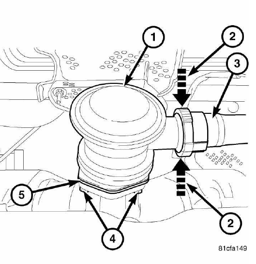
Fig. 19: AIR INJECTION CHECK VALVE
NOTE: Make sure the old gasket material is completely removed from air injection pipe.
1. Install new gasket (5) and air injection check valve (1) to pipe.
2. Install air injection check valve mounting bolts (4).
NOTE: The quick connect fitting on the air outlet tube is slotted to fit the air injection check valve fitting. Line the slot up when making the connection.
3. Install air pump outlet tube (3) to air injection check valve (1) connection. A click noise will indicate a good connection.
4. Install engine cover.
 Tube, air pump, inlet
Description
The air pump inlet tube is located on the left side of the engine
compartment. The tube attaches to the air
injection pump using a quick connect style fitting. The other end of the tub ...

See also:
Electrical
SWITCH, BRAKE FLUID LEVEL
Description
The brake fluid level switch (2) is mounted through the center of the fluid
reservoir. The switch can be serviced
separately from the master cylinder fluid r ...
Removal
BEVERAGE COOLER
WARNING: Disable the airbag system before attempting any steering
wheel, steering
column, or instrument panel component diagnosis or service. Disconnect
and isolate t ...
A/C Performance
The A/C system is designed to provide the passenger compartment with low
temperature and low humidity air.
The A/C evaporator, located in the HVAC housing is cooled to temperatures near
the fre ...
