Dodge Journey: Removal
Two unique brake lamp switches are used in this vehicle, depending upon whether the vehicle was built during early or late production. These switches are not interchangeable. Both switches are illustrated and described elsewhere in this service information to assist in positive identification.
EARLY PRODUCTION
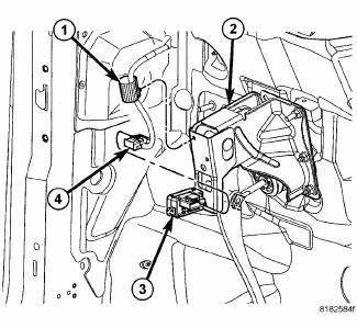
Fig. 62: Stop Lamp Switch Wiring Routing Clip, Brake Pedal Bracket, Stop Lamp
Switch & Wiring
Connector
1. Disconnect and isolate the battery negative cable.
2. If equipped, remove the silencer pad from below the steering column.
3. Locate the brake lamp switch (3) on the brake pedal support bracket (2) under the instrument panel.
4. Disconnect the wire harness connector (4) from the switch.
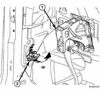
Fig. 63: STOP LAMP SWITCH REMOVAL
1. Rotate the brake lamp switch housing (2) counterclockwise about 30 degrees to align the tabs on the switch locking collar with the keyed hole in the brake pedal support bracket (1).
2. Pull the switch straight rearward from the keyed hole to remove it from the bracket.
3. Discard the removed brake lamp switch. The brake lamp switch self-adjusting plunger is a one time only feature. If the switch is removed from the bracket, it MUST be replaced with a new switch.
LATE PRODUCTION
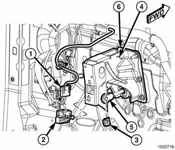
Fig. 64: Brake Lamp Switch On Brake Pedal Support Bracket
1. Disconnect and isolate the battery negative cable.
2. If equipped, remove the silencer pad from below the steering column.
3. Locate the brake lamp switch (2) on the brake pedal support bracket (4) under the instrument panel.
4. Depress and hold the brake pedal in the depressed position.
5. Rotate the brake lamp switch housing (2) counterclockwise about 30 degrees to align the tabs on the switch locking collar with the keyed hole in the brake pedal support bracket.
6. Pull the switch straight rearward from the keyed hole to remove it from the bracket.
7. Release the brake pedal.
8. Disconnect the wire harness connector (1) from the switch.
 Diagnosis and Testing
BRAKE LAMP SWITCH
WARNING: To avoid serious or fatal injury on vehicles equipped
with airbags, disable
the Supplemental Restraint System (SRS) before attempting any steering
wheel, s ...
 Installation
Two unique brake lamp switches are used in this vehicle, depending upon
whether the vehicle was built during
early or late production. These switches are not interchangeable. Both switches
are il ...
See also:
Description, Operation
DESCRIPTION
Fig. 430: Identifying Valve Body Assembly
- VALVE BODY
- T/C REGULATOR VALVE
- L/R SWITCH VALVE
- CONVERTER CLUTCH CONTROL VALVE
- MANUAL VALVE
- CONVERTER CLUTCH SWITCH V ...
Operation
SYSTEM
The Powertrain Control Module (PCM) monitors many different circuits in the
fuel injection, ignition, emission
and engine systems. If the PCM senses a problem with a monitored circuit often ...
Description, Operation
DESCRIPTION
The generator is belt-driven by the engine. It is serviced only as a complete
assembly. If the generator fails for
any reason, the entire assembly must be replaced. The generator produ ...
