Dodge Journey: Holding clutches
DESCRIPTION

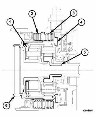
Fig. 356: Identifying 2/4 & Low/Reverse Clutches & Planetary Geartrain
Components
- - FRONT PLANET CARRIER/REAR ANNULUS
- - 2/4 CLUTCH
- - L/R CLUTCH
- - REAR PLANET CARRIER/FRONT ANNULUS
- - REAR SUN GEAR
- - FRONT SUN GEAR ASSEMBLY
Two hydraulically applied multi-disc clutches are used to hold planetary geartrain components (1,4) stationary while the input clutches drive others. The 2/4 (2) and Low/Reverse (3) clutches are considered holding clutches and are contained at the rear of the transaxle case.
OPERATION
NOTE: Refer to ELEMENTS IN USE AT EACH POSITION OF SELECTOR LEVER for a collective view of which clutch elements are applied at each position of the selector lever.
2/4 CLUTCH
The 2/4 clutch is hydraulically applied in Second and Fourth gears by pressurized fluid against the 2/4 clutch piston. When the 2/4 clutch is applied, the front sun gear assembly is held or grounded to the transaxle case.
LOW/REVERSE CLUTCH
The Low/Reverse clutch is hydraulically applied in Park, Reverse, Neutral, and First gears by pressurized fluid against the Low/Reverse clutch piston. When the Low/Reverse clutch is applied, the front planet carrier/rear annulus assembly is held or grounded to the transaxle case.
 Geartrain, planetary
DESCRIPTION
Fig. 355: Identifying Planetary Geartrain Components
- FRONT SUN GEAR ASSEMBLY
- #6 THRUST BEARING
- #7 THRUST BEARING
- REAR CARRIER/FRONT ANNULUS ASSEMBLY
- REAR SUN GEAR
...
 Knob, gearshift
REMOVAL
Fig. 357: Removing/Installing Gearshift Knob
1. Loosen the set screw (3) on the shift knob (2).
2. Hold in the shift knob button (1).
3. Pull up on the shift knob (2) while holding t ...
See also:
REPLACEMENT BULBS
All the inside bulbs are brass or glass wedge base.
Aluminum base bulbs are not approved and should not
be used for replacement.
LIGHT BULBS – Interior Bulb Number
Courtesy/Reading Lamps (Incand ...
Description, Operation
DESCRIPTION
There are two unique park brake switches used on this vehicle, depending upon
whether the vehicle has a foot-operated or hand-operated park brake lever
mechanism.
FOOT-OPERATED
Fi ...
Diagnosis and Testing
Video
VIDEO SYSTEM DIAGNOSIS
CONDITION
POSSIBLE
CAUSES
CORRECTION
NO VIDEO (DVD
PLAYER WILL NOT LOAD OR EJECT)
1. Fuse inoperative.
1. Check fuses. Replace fuse ...
