Dodge Journey: Motor, blower, rear
DESCRIPTION
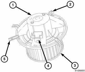
Fig. 191: Rear Blower
The rear blower motor (1) is a 12-volt, direct current (DC) motor mounted within a plastic housing with an integral wire connector (4) and a squirrel cage-type blower wheel (3) that is secured to the blower motor shaft.
Three integral mounting tabs (2) and a lock tab (5) secure the blower motor to the inboard side of the rear heater-A/C housing.
The rear blower motor can be accessed for service without removing the rear heater-A/C housing.
OPERATION
The rear blower motor is used to control the velocity of air moving through the rear heater-A/C housing by spinning the blower wheel within the heater-A/C housing at the selected speed.
The rear blower motor will only operate when the ignition switch is in ON and the rear blower motor switch located in the front accessory switch panel is ON. The rear blower motor receives a battery feed through the totally integrated power module (TIPM), whenever the ignition switch is in ON.
The rear blower motor and blower wheel are factory balanced and cannot be adjusted or repaired and must be replaced as an assembly if inoperative or damaged.
REMOVAL
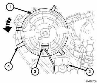
Fig. 192: Rear Blower Motor Remove
1. Disconnect and isolate the negative battery cable.
2. Remove right rear quarter trim panel. 3. Disconnect the wire harness connector (3) from the rear blower motor (1).
4. Disengage the locking tab (4) and remove the rear blower motor from the rear heater-A/C housing (2) by turning the blower motor counterclockwise.
INSTALLATION
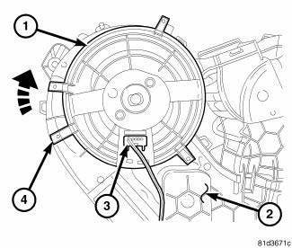
Fig. 193: Rear Blower Motor Install
1. Position the rear blower motor (1) into the rear heater-A/C housing (2) and rotate the blower motor clockwise until the blower motor is fully engaged to the housing and the retaining tab (4) is in the locked position.
2. Connect the wire harness connector (3) to the rear blower motor.
3. Install the right rear quarter trim panel.
4. Reconnect the negative battery cable.
Outlet, air, rear
REMOVAL
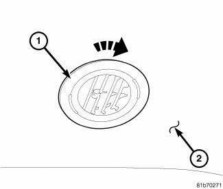
Fig. 194: Ceiling Air Outlet Removal RT
1. Rotate the air outlet (1) being serviced clockwise until the retaining tabs on the back of the outlet disengage from the headliner (2).
2. Remove the air outlet from the headliner.
INSTALLATION
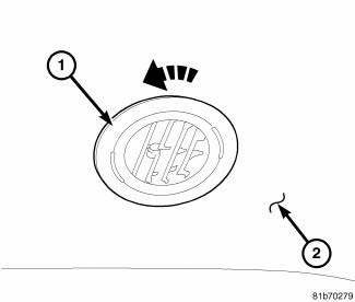
Fig. 195: Ceiling Air Outlet Install RT
1. Position the air outlet (1) being serviced to the opening in the headliner (2).
2. Rotate the air outlet counterclockwise until the retaining tabs on the back of the outlet are fully engaged to the headliner.
 Installation
Fig. 186: Rear Heater AC Housing Removal/Installation
NOTE: MTC rear heater-A/C system shown. ATC system similar.
1. Position the rear heater-A/C housing (1) into the vehicle and align the
...
 Plumbing, front
...
See also:
Duct, ceiling distribution
REMOVAL
WARNING: Disable the airbag system before attempting any steering
wheel, steering
column or instrument panel component diagnosis or service. Disconnect
and isolate the negati ...
Installation
WITH FOOT LEVER
1. Pass most of the front parking brake cable down through the access hole in
the floor pan from inside the
vehicle.
Fig. 195: CABLE HOUSING RETAINED IN LEVER
2. Insert the lev ...
SAFETY TIPS
Transporting Passengers
NEVER TRANSPORT PASSENGERS IN THE CARGO
AREA.
WARNING:
• Do not leave children or animals inside parked
vehicles in hot weather. Interior heat build-up may
cause seriou ...
