Dodge Journey: Description, Operation
DESCRIPTION
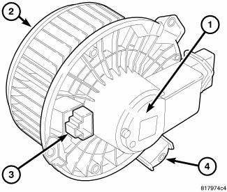
Fig. 139: Blower Motor-PM
The blower motor (1) is used to control the velocity of air moving through the HVAC housing by spinning the blower wheel (2) within the HVAC air inlet housing at the selected speed.
The blower motor is a 12-volt, direct current (DC) motor mounted within a plastic housing with an integral wire harness connector (3) and three mounting tabs (4). The squirrel cage-type blower wheel is secured to the blower motor shaft and is positioned within the air inlet housing on the passenger side of the HVAC housing.
OPERATION
The blower motor controls the velocity of air moving through the HVAC housing by spinning the blower wheel within the HVAC air inlet housing at the selected speed.
On the Manual Temperature Control (MTC) heating-A/C system, blower motor speed is controlled by regulating the path to ground through the blower control switch and the blower motor resistor. With the Automatic Temperature Control (ATC) heating-A/C system, blower motor speed is controlled by an electronic blower motor power module, that uses a Pulse Width Modulated (PWM) input from the A/C-heater control and a feedback signal from the blower motor to regulate the blower motor ground path. On both systems, the blower motor receives battery current through the Totally Integrated Power Module (TIPM) whenever the ignition switch is in the Run position, and the blower motor control is in any position except Off.
The blower motor can be accessed for service from underneath the instrument panel.
NOTE: The blower motor is supplied with a 12 volt feed from the TIPM whenever the ignition switch is in the Run position. Due to an open circuit condition within the blower motor control switch, the TIPM is unable to detect an open circuit for the blower motor.
The blower motor control system is diagnosed using a scan tool.
The blower motor and blower motor wheel are factory balanced as an assembly and cannot be adjusted or repaired and must be replaced if inoperative or damaged.

 Diagnosis and Testing
BLOWER MOTOR
WARNING: Disable the airbag system before attempting any steering
wheel, steering
column, or instrument panel component diagnosis or service. Disconnect
and isolate the ...
See also:
SEATS
Seats are a primary part of the Occupant Restraint System
of the vehicle. They need to be used properly for safe
operation of the vehicle.
WARNING:
• DO NOT allow people to ride in any area of y ...
SUGGESTIONS FOR OBTAINING SERVICE FOR YOUR VEHICLE
Prepare For The Appointment
If you’re having warranty work done, be sure to have the
right papers with you. Take your warranty folder. All
work to be performed may not be covered by the
warranty ...
Control, A/C and heater, rear
DESCRIPTION
The A/C-heater controls allows the driver and front seat passenger and the
intermediate seat passengers the
ability to regulate air temperature as well as fan speed for the rear
heat ...
