Dodge Journey: Module, glow plug
DESCRIPTION
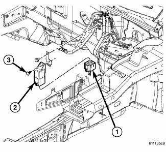
Fig. 23: Locating Diesel Glow Plug Control Module
The glow plug control module is mounted to the fuel filter/water separator bracket, and is controlled by the engine control module.
OPERATION
When the ignition (key) switch is placed in the ON position, a signal is sent to the ECM relating current engine coolant temperature. This signal is sent from the engine coolant temperature sensor.
The glow plug control module receives information about the glow function from the engine control module.
The start of glow plug operation, the period of glow plug operation, the actuation frequency and the pulse duty factor are therefore determined by the engine control module.
REMOVAL

Fig. 24: Locating Diesel Glow Plug Control Module
1. Disconnect the glow plug module harness connector (1)
2. Remove the fastener (3).
3. Remove the glow plug module (2).
INSTALLATION

Fig. 25: Locating Diesel Glow Plug Control Module
1. Install the glow plug module (2).
2. Install the fastener (3).
3. Reconnect the glow plug module harness connector (1)
 Installation
2.4L
Fig. 17: Removing/Installing Ignition Coil
1. Install ignition coil onto spark plug.
Fig. 18: Removing/Installing Ignition Coil Mounting Bolts
2. Install ignition coil mounting bolt, tigh ...
 Plug, glow
DESCRIPTION
Fig. 26: Glow Plug
Glow plugs are used to help start a cold or cool engine. The glow plugs will
heat up and glow to heat the
combustion chamber of each cylinder. An individual glow ...
See also:
Description, Diagnosis and Testing
DESCRIPTION
Fig. 38: Front Hub And Bearing Mounting
The knuckle (3) is a single casting with legs machined for attachment to the
front strut assembly on the top and
steering linkage on the trai ...
Installation
Fig. 25: Ball Joint Installation
1. Install Installer (2), Special Tool 9964-1, and Installer (4), Special
Tool 9964-2 on Remover/Installer (5),
Special Tool 8441-1. Place a new ball joint (stem ...
Installation
CAUTION: Be certain to adjust the refrigerant oil level when
servicing the A/C
refrigerant system. Failure to properly adjust the refrigerant
oil level will prevent the A/C system fro ...
