Dodge Journey: Specifications
2.7L ENGINE
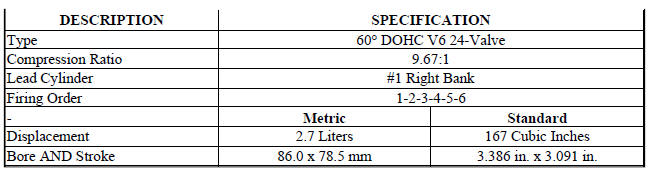
GENERAL SPECIFICATIONS
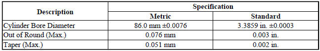
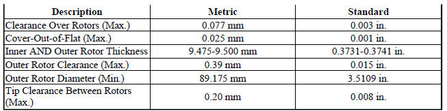
CYLINDER BLOCK
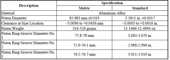
PISTONS
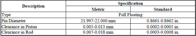
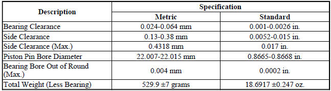
PISTON PINS
PISTON RINGS

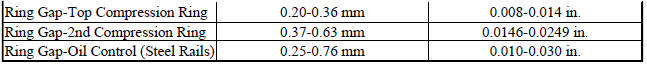
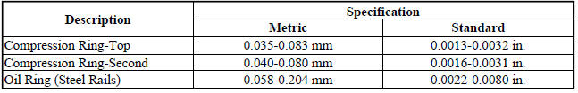
PISTON RING SIDE CLEARANCE
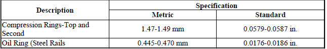
PISTON RING WIDTH
CONNECTING RODS
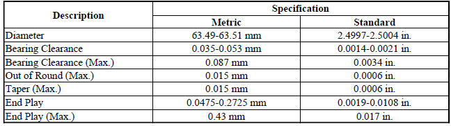
CRANKSHAFT MAIN BEARING JOURNALS
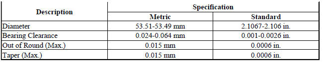
CONNECTING ROD JOURNALS
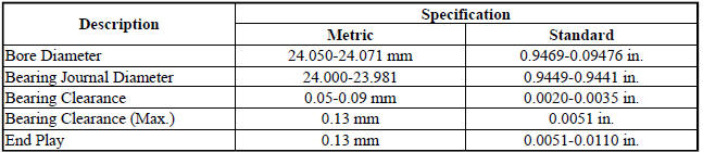
CAMSHAFT
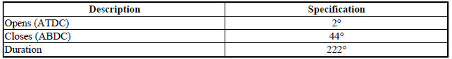
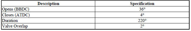
VALVE TIMING-INTAKE VALVES
VALVE TIMING-EXHAUST VALVES
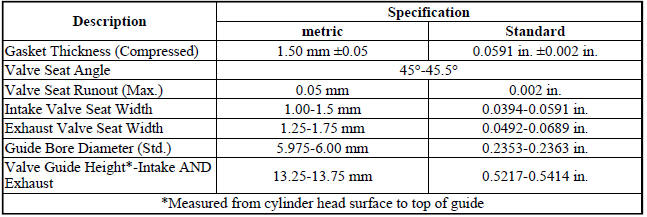
CYLINDER HEAD
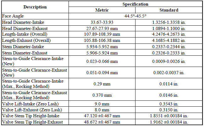
VALVES
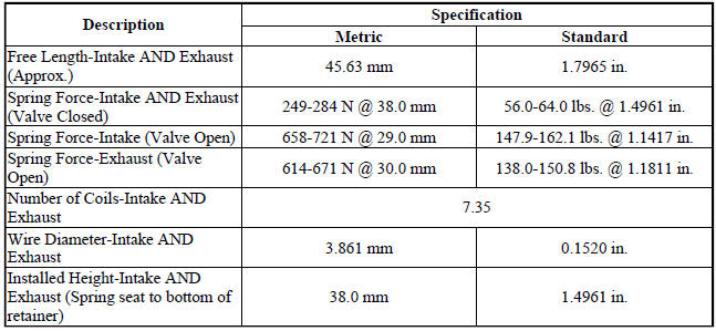
VALVE SPRING
OIL PUMP
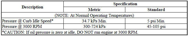
OIL PRESSURE
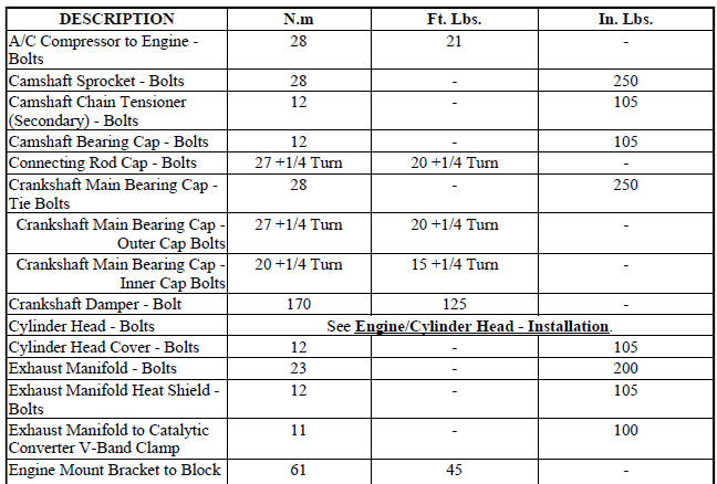
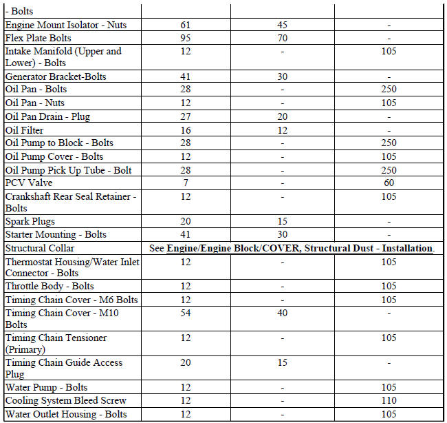
TORQUE
SPECIAL TOOLS
2.7L ENGINE
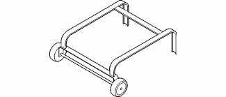
Fig. 53: Dolly 6135
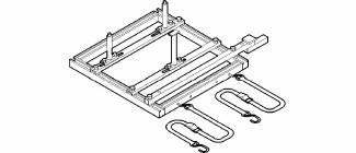
Fig. 54: Cradle 6710
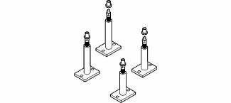
Fig. 55: Post Kit Engine Cradle 6848
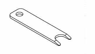
Fig. 56: Disconnect Tool, 6638A
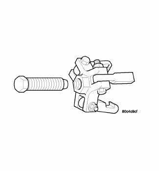
Fig. 57: Puller 8454
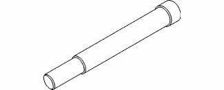
Fig. 58: Crankshaft Damper Remover Insert 8194
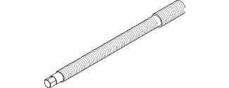
Fig. 59: Crankshaft Damper Installer Screw 8179
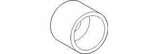
Fig. 60: Crankshaft Damper Installer 6792-1
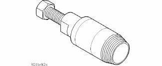
Fig. 61: Crankshaft Seal Remover 6771
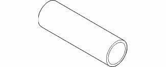
Fig. 62: Crankshaft Seal & Sprocket Installer 6780-1
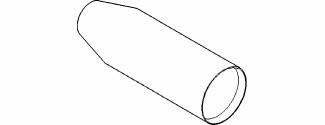
Fig. 63: Crankshaft Seal Protector 6780-2
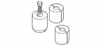
Fig. 64: Puller 5048
Fig. 65: Puller Adaptor 8539
Fig. 66: Crankshaft Rear Seal Guide 6926-1 & Installer 6926-2
Fig. 67: Driver Handle C-4171
Fig. 68: Crankshaft Real Seal Retainer Alignment Fixture 8225

Fig. 69: Timing Chain Tensioner Resetting Gauge 8186
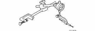
Fig. 70: Dial Indicator C-3339
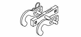
Fig. 71: Valve Spring Compressor 8215-A
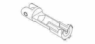
Fig. 72: Adaptor 8216-A

Fig. 73: Valve Spring Compressor C-3422-D
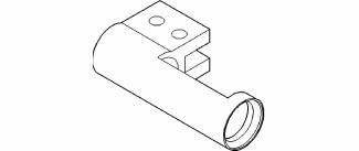
Fig. 74: Valve Spring Adapter 6526
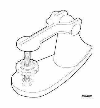
Fig. 75: Valve Spring Tester C-647
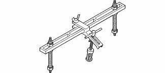
Fig. 76: Valve Spring Compressor MD-998772-A
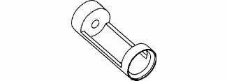
Fig. 77: Valve Spring Adapter 6527
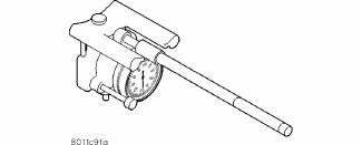
Fig. 78: Indicator Bore Size C-119
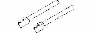
Fig. 79: Connecting Rod Installation Guides 8189
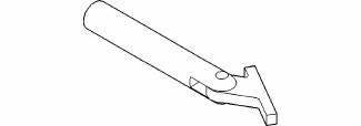
Fig. 80: Main Bearing Remover/Installer C-3059
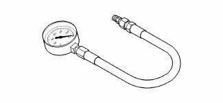
Fig. 81: Pressure Gauge C-3292

Fig. 82: Adapter 8406
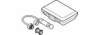
Fig. 83: Cooling System Tester 7700
Fig. 84: Combustion Leak Tester C-3685-A
 Installation
Fig. 32: Brake Booster Vacuum Hose
1. Position engine/transaxle assembly under vehicle and slowly lower vehicle
in short length spans. Inspect
at each interval for potential engine or transaxle ...

See also:
Description, Operation
DESCRIPTION
A diesel particulate filter (DPF) is installed for exhaust gas
after-treatment. The DPF filters, stores and burns
particulate matter (soot) that is generated during the combustion proc ...
Description
Four-wheel disc brakes are standard on this vehicle. Each disc brake assembly
consists of the following major
components:
Caliper
Caliper adapter bracket
Pads (Shoe and lining assemblies)
...
Control, A/C and heater, rear
DESCRIPTION
The A/C-heater controls allows the driver and front seat passenger and the
intermediate seat passengers the
ability to regulate air temperature as well as fan speed for the rear
heat ...
