Dodge Journey: With intermediate shaft
NOTE: The inner tripod joints are designed with a retention feature that prevents the tripod rollers from coming out of the inner joint housing up to a specific load. If this feature is overcome and any of the rollers are pulled past the retention feature the joint will "lock-up" and no longer function properly. The entire halfshaft assembly must be replaced if this occurs.
NOTE: Some halfshafts use a tuned rubber damper weight. When replacing a halfshaft assembly, be sure the replacement halfshaft has the same damper weight as the original.
NOTE: 3.5L Shown in illustration, all others equipped with an intermediate shaft are similar.
NOTE: Care must be taken not to separate the inner C/V joint during this operation. Do not allow halfshaft to hang by inner C/V joint after removing outer C/V Joint from the hub/bearing assembly in steering knuckle, end of halfshaft must be supported.
Fig. 20: Outer C/V Joint Of Half Shaft Assembly
1. Thoroughly clean spline and oil seal sealing surface on tripod joint. Lightly lubricate oil seal sealing surface on tripod joint with fresh clean transmission lubricant.
2. Holding half shaft assembly (1) or (2) by tripod joint and interconnecting shaft, install tripod joint into transaxle side gear (left side) or the intermediate shaft (right side) as far as possible by hand. Be sure to engage splines prior to applying force.
NOTE: Attempt to remove tripod joint by hand to verify that the snap ring is fully engaged. If snap ring is fully engaged, tripod joint will not be removable from transmission by hand.
3. Forcefully push the tripod joint into the transaxle side gear, until snap-ring is fully engaged.
Fig. 21: Outer CV Joint Inspection
4. Clean all debris and moisture out of steering knuckle, in the area were outer CV joint (1) will be installed into steering knuckle.
5. Ensure that front of outer CV joint (2) which fits against the face of the hub and bearing is free of debris and moisture before installing outer CV joint into hub and bearing assembly.
Fig. 22: Strut To Steering Knuckle Attaching Bolts
6. Install the steering knuckle(3) to the strut clevis bracket (1).
7. Install the steering knuckle-to-strut attachment bolts and nuts (2). While holding the bolts in place, tighten the nuts to 140 N.m (103 ft. lbs.)
Fig. 23: Front Brake Mounting
8. Install brake disc (1) onto hub and bearing assembly (2).
9. Install front disc brake caliper (5) and adapter (6) to the steering knuckle (3). Caliper is installed by first sliding bottom of caliper assembly under abutment on steering knuckle, and then rotating top of caliper against top abutment.
10. Install the two bolts (4) that secure the front disc brake caliper and adapter to the steering knuckle.
Tighten the bolts to 169 N.m (125 ft. lbs.).
Fig. 24: View Of Hub Nut & Axle Shaft
NOTE: Always install a new hub nut. The original hub nut is one-time use only and should be discarded when removed.
11. Clean all foreign matter from the threads of the outer CV joint. Install the half shaft to hub/bearing assembly nut (1) onto halfshaft (2).
12. With the brakes applied to keep hub from turning, tighten the hub nut to 160 N.m (118 ft. lbs.).
13. Install front wheel and tire assembly. Install and tighten the wheel mounting stud nuts in proper sequence until all nuts are torqued to half the required specification. Then repeat the tightening sequence to the full specified torque of 135 N.m (100 ft. lbs.).
14. Lower vehicle.
15. Check for correct fluid level in transaxle assembly. 16. If equipped, install the engine belly pan.
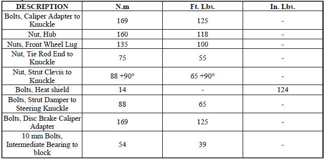
SPECIFICATIONS
TORQUE SPECIFICATIONS
 Without intermediate shaft
NOTE: The inner tripod joints are designed with a retention feature
that prevents the
tripod rollers from coming out of the inner joint housing up to a specific
load. If
this feature is o ...

See also:
Installation
SATELLITE AUDIO ONLY
NOTE: The antenna cables are integrated into the body wiring
harnesses. New antenna
cables is overlaid on the body wiring harness.
1. Route the cable behind the glove ...
Cam, turn signal cancel
DESCRIPTION
The turn signal cancel cam is concealed within the clockspring case on the
steering column. The turn signal
cancel cam consists of integral eccentrics on the outer circumference of the ...
Disassembly
NOTE: The strut assembly must be removed from the vehicle for it to be
disassembled
and assembled.
For the disassembly and assembly of the strut assembly, use strut spring
compressor, tea ...
