Dodge Journey: Sensor, transmission range
DESCRIPTION
Fig. 386: Locating Transmission Range Sensor (TRS)
- - TRANSMISSION RANGE SENSOR
The Transmission Range Sensor (TRS) (1) is mounted to the top of the valve body inside the transaxle and can only be serviced by removing the valve body. The electrical connector extends through the transaxle case.
The Transmission Range Sensor (TRS) has four switch contacts that monitor shift lever position and send the information to the PCM/TCM.
Fig. 387: Identifying Transmission Range Sensor With Integrated Temperature
Sensor
- - TRANSMISSION RANGE SENSOR
- - TEMPERATURE SENSOR
The TRS (1) also has an integrated temperature sensor (thermistor) (2) that communicates transaxle temperature to the TCM and PCM .
OPERATION
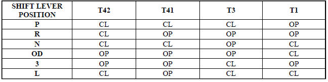
The Transmission Range Sensor (TRS) communicates Shift Lever Position (SLP) to the PCM/TCM as a combination of open and closed switches. Each shift lever position has an assigned combination of switch states (open/closed) that the PCM/TCM receives from four sense circuits. The PCM/TCM interprets this information and determines the appropriate transaxle gear position and shift schedule.
Since there are four switches, there are 16 possible combinations of open and closed switches (codes). Seven of these codes are related to gear position and three are recognized as "between gear" codes. This results in six codes which should never occur. These are called "invalid" codes. An invalid code will result in a DTC, and the PCM/TCM will then determine the shift lever position based on pressure switch data. This allows reasonably normal transmission operation with a TRS failure.
TRS SWITCH STATES
TRANSMISSION TEMPERATURE SENSOR
The TTS has an integrated thermistor that the PCM/TCM uses to monitor the transmission's sump temperature.
Since fluid temperature can affect transmission shift quality and convertor lock up, the PCM/TCM requires this information to determine which shift schedule to operate in. The PCM also monitors this temperature data so it can energize the vehicle cooling fan(s) when a transmission "overheat" condition exists. If the thermistor circuit fails, the PCM/TCM will revert to calculated oil temperature usage.
CALCULATED TEMPERATURE
A failure in the temperature sensor or circuit will result in calculated temperature being substituted for actual temperature. Calculated temperature is a predicted fluid temperature which is calculated from a combination of inputs:
- Battery (ambient) temperature
- Engine coolant temperature
- In-gear run time since start-up
REMOVAL

Fig. 388: Removing/Installing Transmission Range Sensor
- - TRANSMISSION RANGE SENSOR
- - MANUAL VALVE CONTROL PIN
- - RETAINING SCREW
1. Remove valve body assembly from transaxle.
2. Remove Transmission Range Sensor retaining screw (3) and remove sensor (1) from valve body.
3. Remove TRS (1) from manual shaft.
INSTALLATION
Fig. 389: Removing/Installing Transmission Range Sensor
- - TRANSMISSION RANGE SENSOR 2 - MANUAL VALVE CONTROL PIN 3 - RETAINING SCREW
1. Install Transmission Range Sensor (TRS) (1) to the valve body and torque retaining screw (3) to 5 N.m (45 in. lbs.).
2. Install valve body to transaxle.
 Sensor, speed, output
DESCRIPTION
Fig. 378: Identifying Output Speed Sensor
- OUTPUT SPEED SENSOR
The Output Speed Sensor (1) is a two-wire magnetic pickup device that
generates an AC signal as rotation
occurs ...
 Sensor, variable line pressure
DESCRIPTION
Fig. 390: Identifying Variable Line Pressure Sensor
- PRESSURE CONTROL SOLENOID
- LINE PRESSURE SENSOR
- SHOULDER SCREW
- VARIABLE LINE PRESSURE HEADER
- MANUAL SHAFT
- SC ...
See also:
Uconnect™ Multimedia (SIRIUS BACKSEAT TV™) — IF EQUIPPED
Satellite video uses direct satellite receiver broadcasting
technology to provide streaming video. The subscription
service provider is SIRIUS Satellite Radio. SIRIUS Backseat
TV™ offers three vi ...
Toe
Fig. 115: Steering Wheel Holding Tool
1. Center the steering wheel and lock it in place using a steering wheel
clamp.
NOTE: When setting toe, make sure to set rear toe to the preferred
spe ...
Diagnosis and Testing
LAMPS/LIGHTING - EXTERIOR
WARNING: To avoid serious or fatal injury on vehicles equipped
with airbags, disable
the Supplemental Restraint System (SRS) before attempting any steering
...
