Dodge Journey: Disassembly
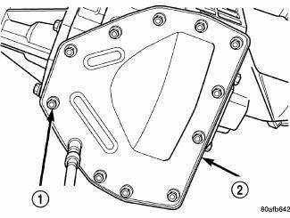
Fig. 314: Removing/Installing Differential Cover Bolts
- - DIFFERENTIAL COVER BOLTS
- - DIFFERENTIAL COVER
NOTE: The transfer shaft should be removed for differential repair and bearing turning torque checking
1. Remove the differential cover bolts (1).
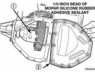
Fig. 315: Identifying Differential Cover
- - DIFFERENTIAL ASSEMBLY
- - DIFFERENTIAL COVER
2. Remove the differential cover (2).
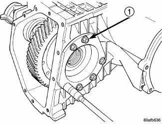
Fig. 316: Removing/Installing Differential Bearing Retainer Bolts
- - DIFFERENTIAL RETAINER BOLTS
3. Remove the differential bearing retainer bolts (1).
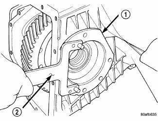
Fig. 317: Removing Differential Bearing Retainer
- - DIFFERENTIAL BEARING RETAINER
- - BEARING PULLER L-4435
4. Remove the differential bearing retainer (1).
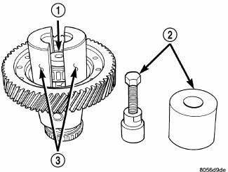
Fig. 318: Removing Differential Bearing Cone On Extension Housing Side
- - THRUST BUTTON L-4539-2
- - PULLER SET 5048
- - COLLETS 5048-4
5. Using a plastic hammer, remove extension housing/adapter plate on the right side of the transaxle.
WARNING: Hold onto differential assembly to prevent it from rolling out of housing.
6. Use Puller Set 5048 (2), 5048-3 Collets (3), and L-4539-2 Button (1) to remove the differential bearing cone on the extension housing side.
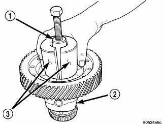
Fig. 319: Installing Puller Set 5048, 5048-4 Collets, & L-4539-2 Button To
Differential Bearing
Cone On Bearing Retainer Side
- - PULLER SET 5048
- - DIFFERENTIAL
- - COLLETS 5048-4
7. Install Puller Set 5048 (1), 5048-4 Collets (3), and L-4539-2 Button to the differential bearing cone on the bearing retainer side.
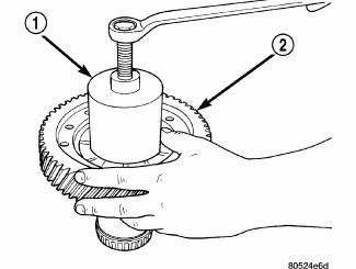
Fig. 320: Removing Differential Bearing Cone On Bearing Retainer Side
- - PULLER SET 5048
- - RING GEAR
8. Remove the differential bearing cone on the bearing retainer side.
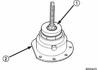
Fig. 321: Installing Special Jaw Set L-4518 & Remover 6062A Onto Differential
Bearing Race
- - REMOVER 6062A
- - DIFFERENTIAL BEARING RETAINER
9. Install Special Jaw Set L-4518 and Remover 6062A (1), onto the differential bearing race from the extension housing.
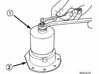
Fig. 322: Removing Differential Bearing Race From Bearing Retainer
- - REMOVER 6062A
- - DIFFERENTIAL BEARING RETAINER
10. Remove the differential bearing race from the bearing retainer (2).
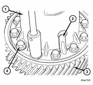
Fig. 323: Identifying Ring Gear-To-Differential Case Bolts & Floating Pinion
Shaft Retainers
- - DIFFERENTIAL CASE
- - PINION SHAFT RETAINER
- - RING GEAR
- - RING GEAR-TO-CASE BOLT
11. Remove ring gear-to-differential case bolts (4) and floating pinion shaft retainers (2).
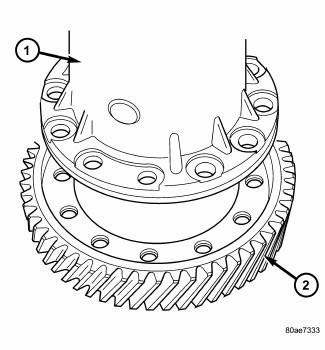
Fig. 324: Identifying Ring Gear & Differential Case
- - DIFFERENTIAL CASE
- - RING GEAR
12. Separate ring gear (2) from differential case (1).
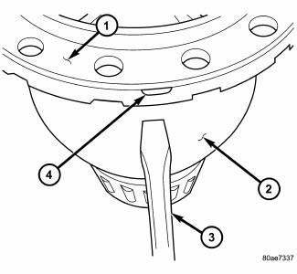
Fig. 325: Identifying Differential Cover At Case
- - DIFFERENTIAL SUPPORT
- - DIFFERENTIAL CASE
- - SCREWDRIVER
- - RELIEF (2 @ 180º APART)
13. Separate differential cover (1) from case (2) using suitable screwdrivers at position.
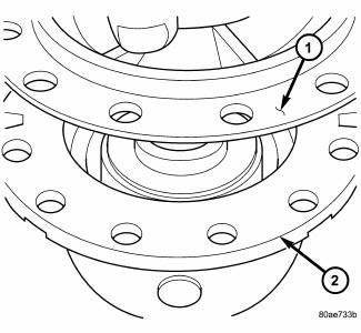
Fig. 326: Identifying Differential Support
- - DIFFERENTIAL SUPPORT
- - DIFFERENTIAL CASE
14. Lift support (1) from case (2) .
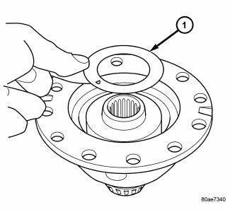
Fig. 327: Removing/Installing Side Gear Thrust Washer
- - SIDE GEAR THRUST WASHER
15. Remove side gear thrust washer (1) .
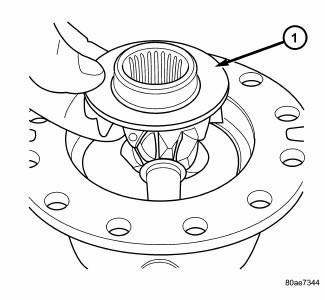
Fig. 328: Removing/Installing Side Gear
- - DIFFERENTIAL SIDE GEAR
16. Remove side gear (1) .
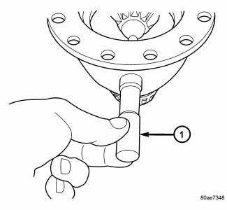
Fig. 329: Removing/Installing Pinion Shaft
- - PINION SHAFT
17. Remove pinion shaft (1) .
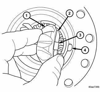
Fig. 330: Removing/Installing Pinion Gears & Tabbed Washers
- - PINION GEAR
- - TABBED WASHER
- - LOCATING TAB
- - NOTCH
18. Remove pinion gears (1) and tabbed washers (2) .
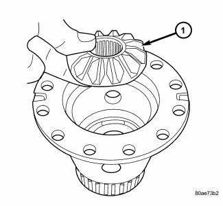
Fig. 331: Removing/Installing Differential Side Gear
- - DIFFERENTIAL SIDE GEAR
19. Remove differential side gear (1) .
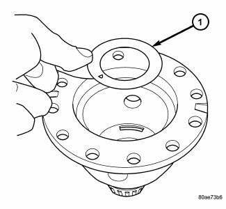
Fig. 332: Removing/Installing Side Gear Thrust Washer
- - THRUST WASHER
20. Remove side gear thrust washer (1) .
21. Inspect all components for excessive wear.
 Description, Operation
DESCRIPTION
Fig. 313: Identifying Differential Assembly
- DIFFERENTIAL CASE
- RING GEAR
- TRANSFER SHAFT
- PINION GEAR
- PINION SHAFT
- SIDE GEAR
The 41TE differential is a convent ...
 Assembly
Fig. 333: Identifying Thrust Washer
- THRUST WASHER
NOTE: The differential is serviced as an assembly. Differential
service is limited to
bearing cups and cones. Any other differentia ...
See also:
Description, Operation
DESCRIPTION
Fig. 284: Rear Evaporator Description
The rear A/C evaporator (4) is located within the rear heater-A/C housing,
behind the right interior quarter panel
trim. The rear A/C evaporato ...
Cooler, EGR
Description
Fig. 62: EGR COOLER
- EGR COOLER TO EGR VALVE TUBE
- MOUNTING SCREWS
- EGR COOLER MOUNTING SCREW
- MOUNTING SCREW
- EGR COOLER BODY
- EGR COOLER MOUNTING NUT
- EGR COOLE ...
Disassembly
NOTE: The strut assembly must be removed from the vehicle for it to be
disassembled
and assembled.
For the disassembly and assembly of the strut assembly, use strut spring
compressor, tea ...
