Dodge Journey: Removal
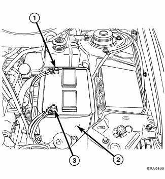
Fig. 10: Identifying Battery Cables
NOTE: If transaxle assembly is being replaced or overhauled (clutch and/or seal replacement), it is necessary to perform the "Quick-Learn" Procedure.
1. Open hood.
2. Disconnect the battery cables (1).
3. Remove the battery hold down bolt and remove the battery (2).
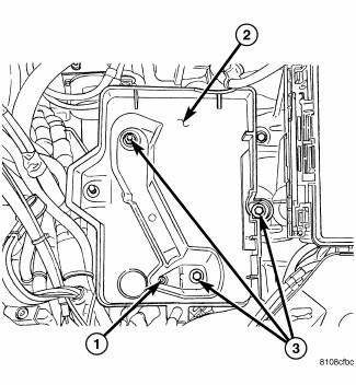
Fig. 11: Removing/Installing Battery Tray
4. Remove the clips holding harness and ground cable to the battery tray.
5. Remove the battery tray hold down bolts (3) and remove the battery tray (2).
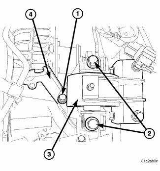
Fig. 12: Identifying Left Mount Bolts
6. Remove the bolts at left mount (1, 2).
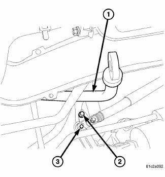
Fig. 13: Removing/Installing Fluid Level Indicator/Tube Assembly
7. Remove the bolt (2) at the fluid level indicator/tube assembly.
8. Remove fluid level indicator/tube assembly (1). Plug opening to prevent debris from entering transaxle.
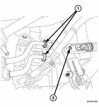
Fig. 14: Identifying Oil Cooler Lines
9. Disconnect oil cooler lines (1) from transaxle using Disconnect Tool 8875A.
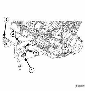
Fig. 15: Identifying Transmission Electrical Connectors
10. Disconnect the electrical connectors at transmission (1, 2, 3, 4 and 5).
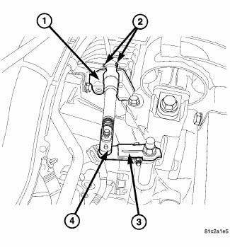
Fig. 16: Identifying Shift Cable At Manual Valve & Cable Bracket
11. Disconnect gear shift cable from manual valve (4) lever and cable bracket (2).
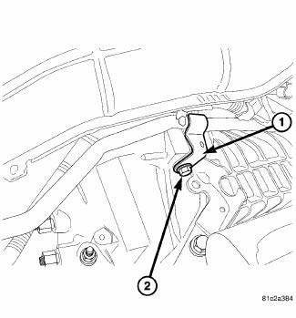
Fig. 17: Identifying Heater Tube Bolt At Bellhousing
12. Remove the heater tube bolt (1) at the bellhousing.
13. Move the heater tube out of the way to gain access to the bellhousing bolts.
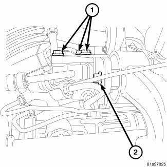
Fig. 18: Identifying Rear Mount Bracket-To-Transaxle Case Bolts
14. Remove rear mount bracket-to-transaxle case bolts (1).
15. Raise vehicle on hoist.
16. Remove transaxle oil pan and drain fluid into suitable container.
17. Remove front wheel/tire assemblies.
18. Remove left and right halfshaft assemblies.
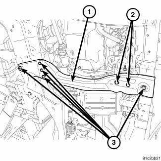
Fig. 19: Removing/Installing Crossmember
19. Support engine with a screw jack and transmission with a transmission jack.
20. Remove the bolts at the crossmember (2, 3).
21. Remove the crossmember (1).
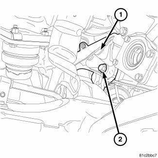
Fig. 20: Removing/Installing Rear Mount Side Bolt
22. Remove the rear mount (1) side bolt (2).
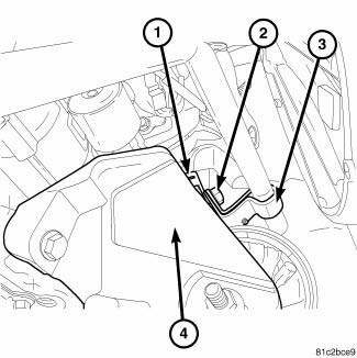
Fig. 21: Identifying Heater Tube & Ground Cable Bolt At Front Mount
23. Remove the bolt (2) holding the ground cable (1) and the heater tube bracket (3) to the front mount (4).
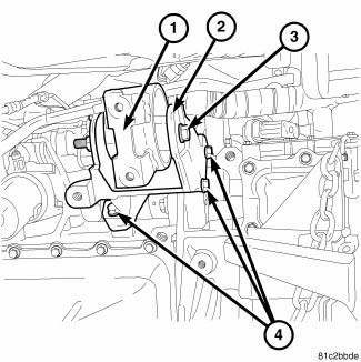
Fig. 22: Removing/Installing Front Transmission Mount
24. Remove the bolts (4) at the front mount (2) 25. Remove the front mount (2).
26. Remove the starter motor.
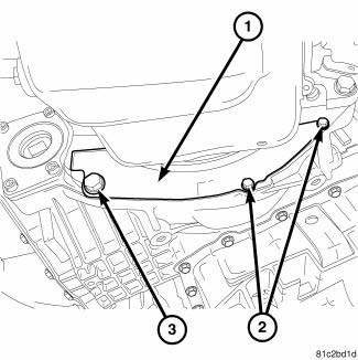
Fig. 23: Removing/Installing Inspection Cover
27. Remove inspection cover bolts (2, 3).
28. Remove inspection cover (1).
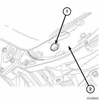
Fig. 24: Removing/Installing Torque Converter-To-Drive Plate Bolts
29. Remove torque converter-to-drive plate bolts (1).
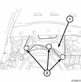
Fig. 25: Removing/Installing Left Mount To Block Bolts
30. Lower engine and transmission enough to gain access to the left mount to block bolts.
31. Remove left mount to block bolts (2).
32. Remove left mount.
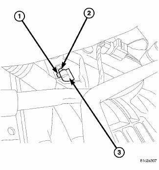
Fig. 26: Removing/Installing CKP Sensor
33. Unplug the electrical connector (3) at the CKP sensor (2).
34. Remove the bolt (1) at the CKP sensor.
35. Remove CKP sensor (2).
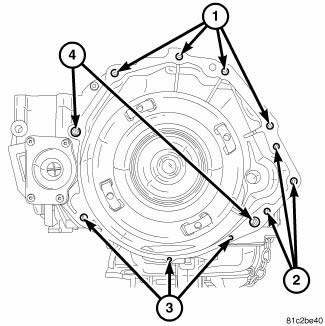
Fig. 27: Removing/Installing Bellhousing Upper & Lower Bolts
36. Remove the bellhousing upper (1) and lower bolts (2) from transmission.
37. Remove transaxle assembly from vehicle.
 Clutch air pressure tests
Fig. 6: Identifying Air Pressure Test Plate Tool 6056
- AIR PRESSURE TEST PLATE TOOL 6056
- ACCUMULATORS
Inoperative clutches can be located using a series of tests by substituting
air pr ...
 Disassembly
Fig. 28: Identifying Solenoid/Pressure Switch Assembly & Gasket
- SOLENOID/PRESSURE SWITCH ASSEMBLY
- GASKET
NOTE: If transaxle is being overhauled (clutch and/or seal
replacement ...
See also:
JUMP-STARTING
If your vehicle has a discharged battery it can be jumpstarted
using a set of jumper cables and a battery in
another vehicle or by using a portable battery booster
pack. Jump-starting can be danger ...
Description - monitored component
There are several components that will affect vehicle emissions if they
malfunction. If one of these components
malfunctions the Malfunction Indicator Lamp (Check Engine) will illuminate.
Some o ...
Installation
BULBS
HEADLAMP HIGH BEAM
CAUTION: Always use the correct bulb size and type for
replacement. An incorrect
bulb size or type may overheat and cause damage to the lamp, the socket
or ...
