
Dodge Journey: Description, Operation
DESCRIPTION
A Macpherson type design strut assembly is used in place of the traditional front suspension upper control arm and upper ball joint. The bottom of the strut mounts directly to the steering knuckle using two attaching bolts and nuts going through the strut clevis bracket and knuckle. The top of the strut mounts directly to the strut tower of the vehicle using the three threaded studs on the strut assembly's upper mount.
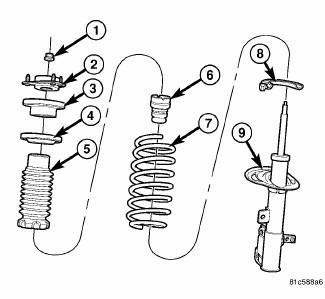
Fig. 79: Strut Assembly (Exploded)
The strut assembly includes the following components:
- Upper mount (2)
- Bearing and upper spring seat (3)
- Upper spring isolator (4)
- Dust shield (5)
- Jounce bumper (6)
- Coil spring (7)
- Lower spring isolator (8)
- Strut (damper) (9)
Each component is serviced by removing the strut assembly from the vehicle and disassembling it.
Coil springs are rated separately for each corner or side of the vehicle depending on optional equipment and type of vehicle service. If a coil spring requires replacement, be sure that it is replaced with a spring meeting the correct load rating for the vehicle and its specific options.
OPERATION
The strut assembly cushions the ride of the vehicle, controlling vibration, jounce and rebound of the suspension.
The coil spring controls ride quality and maintains proper ride height.
The spring isolators isolate the coil spring at the top and bottom from coming into metal-to-metal contact with the upper mounting seat and the strut.
The jounce bumper limits suspension travel and metal-to-metal contact under full jounce condition.
The strut dampens jounce and rebound motions of the coil spring and suspension.

 Diagnosis and Testing
STRUT ASSEMBLY
Fig. 80: Strut Assembly (Exploded)
Inspect the strut assembly for the following conditions:
Inspect for a damaged or broken coil spring (7).
Inspect for a torn or damaged dust ...
See also:
Standard procedure
SPIRAL CELL BATTERY CHARGING
WARNING: Never exceed 14.4 volts when charging a spiral cell
battery. Personal
injury and/or battery damage may result.
Vehicles equipped with a diese ...
Valve, one way check
Description
Fig. 16: AIR INJECTION CHECK VALVE
The air injection check valve (1) is a one-valve check valve that allows air
to flow in one direction only. The
valve is located at exhaust side o ...
Description, Operation
DESCRIPTION
Fig. 265: A/C Expansion Valve Description KA
The A/C expansion valve controls the amount of refrigerant entering the A/C
evaporator. The A/C expansion
valve is of a thermostatic exp ...
