Dodge Journey: Valve, exhaust gas recirculation (EGR)
Description
The EGR valve consists of three major components. First there is the pintle, valve seat, and housing which contains and regulates the gas flow. Second there is the armature, return spring, and solenoid coil to provide the operating force to regulate the flow by changing the pintle position. The solenoid coil assembly is in parallel with a diode and connects to the two connectors in the connector assembly. The third major component which senses pintle position and is connected to the three connectors in the electrical connector.
Operation
The exhaust gas recirculation flow is determined by the engine controller. For a given set of conditions, the engine controller knows the ideal exhaust gas recirculation flow to optimize NOx and fuel economy as a function of the pintle position. Pintle position is obtained from the position sensor. The engine controller adjusts the duty cycle of 128 Hz power supplied to the solenoid coil to obtain the correct position.
Removal
2.7L
Fig. 65: Exhaust Gas Recirculation System
WARNING: The normal operating temperature of the exhaust gas recirculate (EGR) valve and tube is very high. Therefore, never work around or attempt to service any engine component until it is completely cooled.
NOTE: It is very important to disconnect the battery due to the addresses (cells) within the engine controller that store learned values related to powertrain operation.
A malfunctioning EGR system can cause bad values to be stored in these cells that can cause an erroneous fault to occur after the system is repaired.
Disconnecting the battery for at least two minutes will remove all power from the controller and reset these cells to normal default values.
1. EGR system components and location. Upper tube (2), EGR valve (1), and Lower tube (3).
2. Disconnect negative battery cable.
3. Unlock and disconnect the electrical connector from EGR valve.

Fig. 66: Exhaust Gas Recirculation Valve
4. Remove the bolts from the EGR tube to exhaust manifold.
5. Remove the lower tube bolts to EGR valve and remove tube (3).
6. Remove upper tube bolts to EGR valve (2).
7. Remove the EGR valve mounting bolts (1).
8. Remove valve from vehicle.
9. Clean mounting surface.
3.5L
Fig. 67: Exhaust Gas Recirculation Valve/Solenoid Removal - 4.0L
WARNING: The normal operating temperature of the exhaust gas recirculate (EGR) valve and tube is very high. Therefore, never work around or attempt to service any engine component until it is completely cooled.
NOTE: It is very important to disconnect the battery due to the addresses (cells) within the engine controller that store learned values related to powertrain operation.
A malfunctioning EGR system can cause bad values to be stored in these cells that can cause an erroneous fault to occur after the system is repaired.
Disconnecting the battery for at least two minutes will remove all power from the controller and reset these cells to normal default values.
1. Disconnect and isolate negative battery cable at battery.
2. Remove EGR tube bolts (3) at exhaust gas recirculate (EGR) valve (2).
3. Remove EGR tube (4) from EGR valve (2).
4. Remove and discard gasket (5) located between EGR valve (2) and EGR tube (4).
5. Disconnect electrical connector at EGR valve (2).
6. Remove EGR valve mounting bolts (6).
7. Remove EGR valve (2) from cylinder head (1).
8. Remove and discard gasket located between EGR valve (2) and cylinder head (1).
Installation
Fig. 68: Exhaust Gas Recirculation Valve
1. Clean mounting surface.
2. Install EGR valve.
3. Install the EGR valve mounting bolts (1).
4. Install new gasket between the EGR valve and upper tube and install bolts (2).
5. Install the lower tube to exhaust manifold.
6. Install new gasket between the EGR valve and lower tube and install bolts (3).
7. Tighten the lower tube to EGR valve bolts (3) to 12 N.m (106 in. lbs.).
8. Tighten the lower tube to exhaust manifold nuts to 70 N.m (51.5 ft. lbs.).
9. Tighten the upper tube to EGR valve bolts (2) to 12 N.m (106 in. lbs.).
10. Tighten EGR valve to cylinder head bolts (1) to 31 N.m (275 in. lbs.).
11. Tighten the upper tube to intake manifold bolts to 5 N.m (45 in. lbs.).
12. Connect the electrical connector to EGR valve and lock.
13. Connect negative battery cable and tighten nut to 5 N.m (45 in. lbs.).
3.5L
Fig. 69: Exhaust Gas Recirculation Valve Gasket
1. Install new exhaust gas recirculate (EGR) valve gasket to EGR valve.

Fig. 70: Exhaust Gas Recirculation Valve/Solenoid Removal - 4.0L
2. Install EGR valve (2), gasket and bolts (6) to cylinder head (1). Tighten to 31 N.m (23 ft. lbs.).
3. Install new gasket (5), EGR tube (4) and bolts (3) to EGR valve (2). Tighten to 12 N.m (106 in. lbs.).
4. Tighten the EGR tube to intake manifold bolts to 5 N.m (45 in. lbs.).
5. Connect electrical connector to EGR valve (2).
6. Connect negative battery cable, tighten nut to 5 N.m (45 in. lbs.).
SPECIFICATIONS
TORQUE
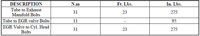
 Tube, exhaust gas recirculation (EGR)
Removal
2.7L - LOWER TUBE
Fig. 50: Lower Exhaust Gas Recirculation Tube - 2.7L
WARNING: The normal operating temperature of the exhaust gas
recirculate (EGR)
valve and tube is very ...

See also:
Diagnosis and testing
ON-BOARD DIAGNOSTIC SYSTEM
The Powertrain Control Module (PCM) monitors critical input and output
circuits of the charging system,
making sure they are operational. A Diagnostic Trouble Code (DTC) ...
Description
Fig. 246: Liquid/Suction Line Assembly with Rear A/C
NOTE: A/C liquid and suction line assembly with rear A/C shown. Front
A/C only line
assembly similar.
The A/C liquid line is serviced ...
JACKING AND TIRE CHANGING
WARNING:
• Do not attempt to change a tire on the side of the
vehicle close to moving traffic. Pull far enough off
the road to avoid the danger of being hit when
operating the jack or changing t ...
