Dodge Journey: Installation
Fig. 67: Seal Protector
- - HALFSHAFT
- - SEAL PROTECTOR
1. Install driveline module to transmission jack. Secure module to jack.
2. Using Seal Protector 9099 (2), load halfshafts to differential, one side at a time. Clean tool and seal area to prevent debris intrusion.
Fig. 68: Support Module With Jack
- - DRIVELINE MODULE
- - TRANSMISSION JACK
3. Raise driveline module (1) into position.

Fig. 69: Removing /Installing Propeller Shaft
4. Align marks (4) on propeller shaft rubber coupler (1) to rear axle input flange (5).
5. Install three rear propeller shaft to rear axle retaining bolts (3) but do not tighten at this time.
Fig. 70: RDA To Crossmember Bolts
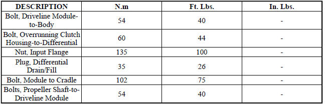
6. Install the RDA - to - crossmember mounting bolts (1) and tighten to 102 N.m (75 ft. lbs.).

Fig. 71: Rear RDA Module-To-Crossmember Bolt
7. Install the rear RDA - to - crossmember mounting bolt (2) to 102 N.m (75 ft. lbs.)
8. Tighten propeller shaft-to-driveline module bolts to 58 N.m (43 ft.lbs.).
9. Raise exhaust system into position and install hanger/brackets.
10. Fill differential with 0.7L (0.74 Quarts) of Mopar Gear and Axle Lubricant (75W-90).
SPECIFICATIONS
SPECIAL TOOLS
Fig. 72: Flange Wrench, C-3281
Fig. 73: Installer 8493
Fig. 74: Installer 9231A
Fig. 75: Protector, 9099
Fig. 76: Universal Handle C-4171
 Removal
Fig. 60: Support Module With Jack
- DRIVELINE MODULE
- TRANSMISSION JACK
NOTE: Rear suspension and drivetrain design require this procedure to
be performed
on a "drive-on" ...
 Case assembly, differential
DESCRIPTION
The differential gear system divides the torque between the axle shafts. It
allows the axle shafts to rotate at
different speeds when turning corners.
Each differential side gear is s ...
See also:
Crankshaft
Description
The crankshaft is constructed of a forged micro alloy steel. The six throw,
nine counterweight crankshaft is
supported by four select fit main bearings with the number three serving as ...
LIFTGATE
The liftgate can be unlocked or locked with the Remote
Keyless Entry (RKE) transmitter or by activating the
power door lock switch located on either front door trim
panel.
NOTE: The liftgate canno ...
Description, Operation
DESCRIPTION
Fig. 4: Rear View Camera
The Rear View Camera (RVC) (4) (also known as ParkView), is a camera on chip
device utilizing
Complementary Metal Oxide Semiconductor (CMOS) technology. CMO ...
