Dodge Journey: Description

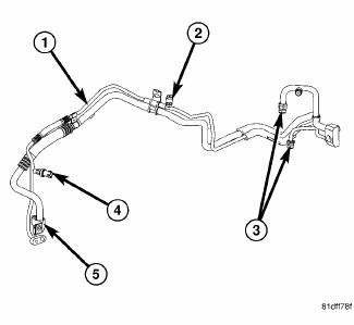
Fig. 246: Liquid/Suction Line Assembly with Rear A/C
NOTE: A/C liquid and suction line assembly with rear A/C shown. Front A/C only line assembly similar.
The A/C liquid line is serviced in two sections. The front section of the A/C liquid line is the refrigerant line that carries liquid refrigerant from the A/C condenser to the A/C receiver/drier and is only serviced as an assembly with receiver/drier. The rear section of the A/C liquid line (1) carries liquid refrigerant from the A/C receiver/drier to the A/C expansion valve and includes the high side service port (2) and a fitting for the A/C pressure transducer (4). The rear section of the A/C liquid line is only serviced as an assembly with the A/C suction line (5). When equipped with rear A/C, the A/C liquid and suction line assembly includes connections for the underbody refrigerant lines (3).
NOTE: Replacement of the refrigerant line O-ring seals and gaskets is required anytime a refrigerant line is disconnected. Failure to replace the rubber O-ring seals and metal gaskets could result in a refrigerant system leak.
The A/C liquid and suction line assembly has no serviceable parts except for the metal gaskets, rubber O-ring seals and the service port valve cores. The O-ring seals used on the connections are made from a special type of rubber not affected by R-134a refrigerant. The O-ring seals and gaskets must be replaced whenever the A/C liquid/suction line assembly is disconnected.
The A/C liquid and suction line assembly cannot be repaired and must be replaced if leaking or damaged.
 Line, A/C liquid
...
 Removal
WARNING: Review safety precautions and warnings in this part
before performing
this procedure. See Heating and Air Conditioning/Plumbing - Warning
and. Failure to
follow the warnin ...
See also:
Crossmember, front fore and aft
REMOVAL
1. Raise and support the vehicle.
2. If equipped, remove the engine belly pan.
Fig. 29: Removing/Installing Fore/Aft Crossmember
3. Remove the front engine mount thru-bolt (2).
Fig ...
Installation
LEFT-HAND DRIVE
1. Clean any debris off the mating surfaces of the HCU and ABM.
CAUTION: When installing new O-rings or solenoid valve stem seals,
do not use
any type of lubricant.
...
Insulator, engine mount, left
Removal
Fig. 228: Belly Pan
1. Disconnect and isolate the negative battery cable.
2. Remove throttle body air inlet hose and air cleaner housing assembly.
3. Remove the belly pan (2).
...
