Dodge Journey: Description, Operation, Diagnosis and Testing
DESCRIPTION
The lubrication system is a full-flow filtration, pressure feed type. The oil pump body is mounted to the engine block. The pump inner rotor is driven by the crankshaft. A structural windage tray is used to increase power by minimizing oil windage at high engine RPM. An engine oil cooler is used on some models.
OPERATION
Oil from the oil pan is pumped by a gerotor type oil pump (3) directly coupled to the crankshaft. Oil pressure is controlled by a relief valve mounted inside the oil pump housing.
Fig. 247: Cylinder Block Oil Lubrication System
- - TO RIGHT CYLINDER HEAD
- - TO LEFT CYLINDER HEAD
- - OIL PUMP
- - OIL PICKUP TUBE
- - OIL FILTER
- - TO CRANKSHAFT MAIN JOURNALS
- - MAIN OIL GALLERY
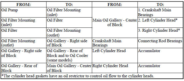
Fig. 248: Cylinder Head Oil Lubrication System - Left Side
- - CAM JOURNALS
- - OIL FEED TO CAMSHAFT (SECONDARY) CHAIN TENSIONER
- - LASH ADJUSTER BORES
- - OIL FEED FROM BLOCK
- - VENT HOLE
- - ACCUMULATOR
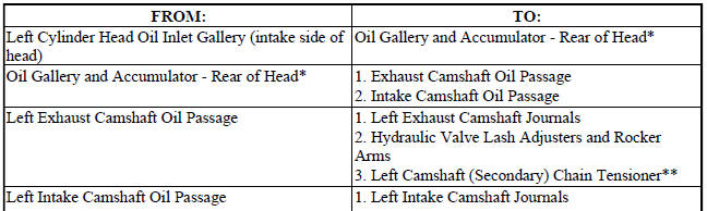
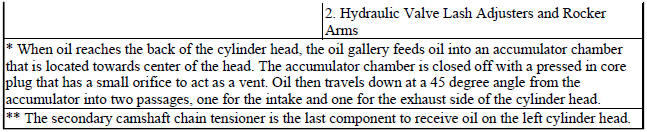
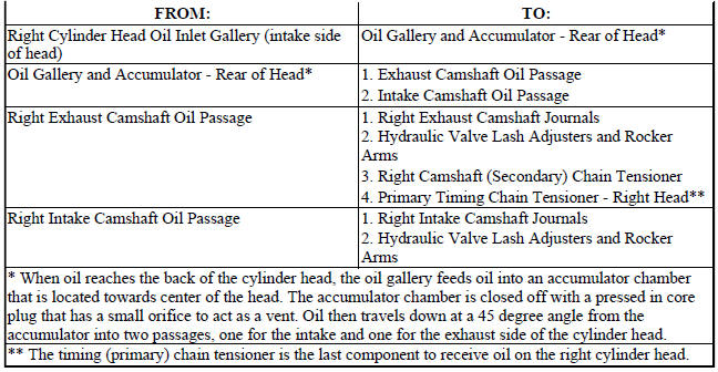
Fig. 249: Cylinder Head Oil Lubrication System - Right Side
- - OIL FEED TO CAMSHAFT (SECONDARY) CHAIN TENSIONER
- - OIL FEED TO TIMING CHAIN (PRIMARY) TENSIONER
- - CAM JOURNALS
- - ACCUMULATOR
- - VENT HOLE
- - OIL FEED FROM BLOCK
- - LASH ADJUSTOR BORES

DIAGNOSIS AND TESTING
CHECKING ENGINE OIL PRESSURE
1. Remove the oil pressure switch.
2. Install oil pressure test gauge assembly, Special Tools C-3292A with 8406 adaptor.
3. Start engine and monitor gauge readings.
CAUTION: If oil pressure is 0 at idle, Do Not Run engine at 3000 RPM
4. Oil Pressure (engine at operating temperature): Curb Idle 34.5 kPa (5 psi) minimum 3000 RPM 300-724 kPa (45-105 psi).
5. If oil pressure is 0 at idle. Shut off engine, check for pressure relief valve stuck open or a clogged oil pickup screen.
6. Install oil pressure switch after testing is completed.
 Lubrication
...
 Cooler and lines, oil
Description
Fig. 250: Oil Cooler Fasteners
Some 2.7L engines may be equipped with an engine oil cooler (2) that is
mounted to the rear transmission
mount bracket. Oil lines route oil from the e ...
See also:
Solenoid, exhaust gas recirculation (EGR), 2.0L Diesel
Description
Fig. 71: Exhaust Gas Recirculation (EGR) Solenoid - 2.0L Diesel
- EGR solenoid electrical connector
- EGR vacuum harness
The EGR solenoid (4) is mounted to a bracket attached t ...
Installation
DIESEL PARTICULATE FILTER
Fig. 12: Engine Support Bracket Bolts
1. Position the DPF and turbocharger gasket into the vehicle. Do not tighten
at this time
2. Tighten the three bolts (1) at the ...
Assembly
Fig. 257: Installing Input Shaft
- INPUT SHAFT
- ARBOR PRESS
- INPUT SHAFT HUB ASSEMBLY
Use petrolatum on all seals to ease assembly of components.
1. Using an arbor press (2), install ...
