Dodge Journey: Removal, Installation
REMOVAL
WARNING: To avoid serious or fatal injury on vehicles equipped with airbags, disable the Supplemental Restraint System (SRS) before attempting any steering wheel, steering column, airbag, seat belt tensioner, impact sensor, or instrument panel component diagnosis or service. Disconnect and isolate the battery negative (ground) cable, then wait two minutes for the system capacitor to discharge before performing further diagnosis or service.
This is the only sure way to disable the SRS. Failure to take the proper precautions could result in accidental airbag deployment.
FOOT-OPERATED

Fig. 54: Park Brake Lever Mechanism
1. Disconnect and isolate the battery negative cable.
2. Apply the parking brake.
3. Reach under the left end of the instrument panel to access and disconnect the wire harness connector from the terminal of the park brake switch (2) located on the park brake lever mechanism (1) on the left cowl side inner panel.
4. Remove the screw (3) that secures the park brake switch to the park brake lever mechanism.
5. Remove the switch from the park brake lever mechanism.
HAND-OPERATED

Fig. 55: Parking Brake Lever
1. Disconnect and isolate the battery negative cable.
2. Remove the console from the floor panel transmission tunnel. 3. Pull the parking brake lever (1) upward to apply the parking brake.
4. Disconnect the wire harness connector from the terminal of the park brake switch (2) located on the right side of the park brake lever mechanism.
5. Remove the screw (3) that secures the switch to the park brake lever bracket.
6. Remove the switch from the park brake lever bracket.
INSTALLATION
WARNING: To avoid serious or fatal injury on vehicles equipped with airbags, disable the Supplemental Restraint System (SRS) before attempting any steering wheel, steering column, airbag, seat belt tensioner, impact sensor, or instrument panel component diagnosis or service. Disconnect and isolate the battery negative (ground) cable, then wait two minutes for the system capacitor to discharge before performing further diagnosis or service.
This is the only sure way to disable the SRS. Failure to take the proper precautions could result in accidental airbag deployment.
FOOT-OPERATED
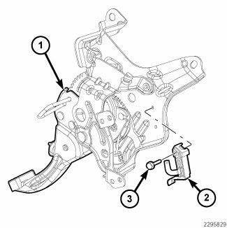
Fig. 56: Park Brake Lever Mechanism
1. Reach under the left end of the instrument panel to position the park brake switch (2) onto the park brake lever mechanism (1) on the left cowl side inner panel. Be certain to engage the locating pin on the back of the switch insulator into the locating slot in the lever mechanism bracket.
2. Install and tighten the screw (3) that secures the park brake switch to the park brake lever mechanism.
Tighten the screw to 2.5 N.m (24 in. lbs.).
3. Reconnect the wire harness connector to the terminal of the park brake switch.
4. Reconnect the battery negative cable.
5. Turn the ignition switch to the ON position and check for proper brake indicator operation with the parking brake applied, then release the parking brake and check that the brake indicator extinguishes.
HAND-OPERATED
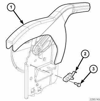
Fig. 57: Parking Brake Lever
1. Position park brake switch (2) onto the right side of the park brake lever (1) bracket. Be certain to engage the locating pin on the back of the switch insulator into the locating slot in the lever bracket.
2. Install and tighten the screw (3) that secures the switch to the lever bracket. Tighten the screw to 2.5 N.m (24 in. lbs.).
3. Reconnect the wire harness connector to the terminal of the switch.
4. Reinstall the console onto the floor panel transmission tunnel.
5. Reconnect the battery negative cable.
6. Turn the ignition switch to the ON position and check for proper brake indicator operation with the parking brake applied, then release the parking brake and check that the brake indicator extinguishes.
 Diagnosis and Testing
PARK BRAKE SWITCH
WARNING: To avoid serious or fatal injury on vehicles equipped
with airbags, disable
the Supplemental Restraint System (SRS) before attempting any steering
wheel, s ...

See also:
Switch, evaporative emissions system monitor
Operation
Fig. 29: Evaporative Emissions System Monitor Switch
- Intake Manifold
- Throttle Body
- Purge Solenoid
- Filter
- ESIM
- Vapor Canister
- Control Valve
- Fuel Tank
- ...
Removal
Fig. 2: Engine Cover
Remove the engine cover.
1. Disconnect battery negative cable.
2. Remove air inlet tube (2) and air cleaner assembly (4).
Fig. 3: Bleeder At Slave Cylinder
3. Remove ...
Description, Operation, Diagnosis and Testing
DESCRIPTION
Fig. 1: Accessory Switch Bank Module
Vehicles with the heated seat option can be visually identified by the two
heated seat switches (1) located in the
center stack of the instrumen ...
