Dodge Journey: Installation
NOTE: Before stabilizer bar installation, inspect the cushions and links for excessive wear, cracks, damage and distortion. Replace any pieces failing inspection.
NOTE: Before installing the stabilizer bar, make sure the bar is not upside-down. The stabilizer bar must be installed so that when in mounted position, the ends of the bar curve under the steering gear tie rods, up to the links.
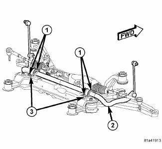
Fig. 72: Stabilizer Bar Mounting
1. Install the stabilizer bar, link ends first, from the rear over top of the crossmember. Curve the ends of the bar (2) under the steering gear.
2. Install the two cushions (bushings) on the stabilizer bar utilizing the slit cut into the cushion sides.
3. Install the two stabilizer bushing retainers (3) over the cushions.
4. Install the screws (1) securing the stabilizer bushing retainers (3) to the crossmember. Tighten all four stabilizer bar cushion retainer screws to 60 N.m (44 ft. lbs.).
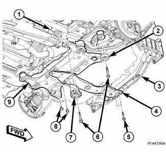
Fig. 73: Front Crossmember Mounting
5. Slowly raise the crossmember (9) into mounted position using the transmission jack matching the crossmember to the marked locations on the body made during removal.
6. Position the front crossmember reinforcement brackets (7) (one each side of vehicle) over the crossmember rear mounting bushings and install the mounting screws (8), but do not tighten at this time.

Fig. 74: Front Crossmember Mounting
7. Install the four mounting bolts (6) securing the front crossmember (1) to the body. Tighten the crossmember mounting bolts to 135 N.m (100 ft. lbs.).
8. Tighten the crossmember reinforcement bracket mounting screws (8) to 50 N.m (37 ft. lbs.).
9. Remove the transmission jack.
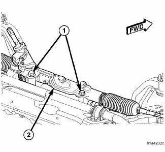
Fig. 75: Identifying Steering Gear Mounting
10. Remove the bungee cord or other supporting the steering gear (2).
11. Install the two bolts (1) securing the steering gear (2) to the crossmember. Tighten the steering gear mounting bolts to 100 N.m (74 ft. lbs.).
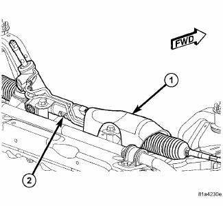
Fig. 76: Heat Shield
12. Position the heat shield (1) over the steering gear (2). Install the mounting screws and push-pins. Tighten the screws to 6 N.m (53 in. lbs.).
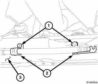
Fig. 77: Hoses At Rear Of Crossmember
13. Position the power steering hose routing clamps (2) on the crossmember. Install and tighten the screws to 8 N.m (71 in. lbs.).
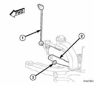
Fig. 78: Stabilizer Link Mounting To Bar
14. Attach the stabilizer bar link (1) at each end of the stabilizer bar (2). At each link, install and tighten the nut (3) while holding the stabilizer bar link lower stud stationary. Tighten the nuts to 48 N.m (35 ft. lbs.).
15. Install the rear engine mount.
16. Install the front engine mount through-bolt.
17. If equipped, install the engine belly pan.
18. Lower the vehicle.
 Removal
1. Raise and support the vehicle.
2. If equipped, remove the engine belly pan.
3. Remove the rear engine mount.
4. Remove the front engine mount through-bolt.
Fig. 66: Stabilizer Link Mo ...

See also:
Description
Fig. 253: Upper Suction/Liquid Line Assembly
NOTE: A/C Suction line for 2.7L engine shown. Other engines similar.
The A/C suction line carries refrigerant from the A/C expansion valve to the ...
Installation
Fig. 137: Rear Mount Bracket
1. If transmission brackets were removed or transmission was replaced install
the rear mount bracket and
tighten (1) to 100 N.m (74 ft. lbs.).
Fig. 138: Front Mou ...
Installation
Fig. 404: Identifying Shifter Mounting Bolts
1. Install the shifter mounting bolts and tighten to 20 N.m (15 ft. lbs.) in
the proper sequence as indicated on
drawing.
Fig. 405: Identifying Sh ...
