Dodge Journey: Removal, Installation
REMOVAL
WARNING: Disable the airbag system before attempting any steering wheel, steering column or instrument panel component diagnosis or service. Disconnect and isolate the negative battery (ground) cable, then wait two minutes for the airbag system capacitor to discharge before performing further diagnosis or service. This is the only sure way to disable the airbag system. Failure to follow these instructions may result in accidental airbag deployment and possible serious or fatal injury.
NOTE: The blower motor is located on the bottom of the passenger side of the HVAC housing. The blower motor can be removed from the vehicle without having to remove the HVAC housing.

Fig. 140: Blower Motor-Removal/Installation
NOTE: LHD model shown. RHD model similar.
1. Disconnect and isolate the negative battery cable.
2. If equipped, remove the silencer from below the passenger side of the instrument panel.
3. From underneath the instrument panel, disengage the connector lock and disconnect the instrument panel wire harness connector (1) from the blower motor (2).
4. Remove the three screws (3) that secure the blower motor and the wire lead bracket (4) (if equipped) to the bottom of the HVAC housing (5) and remove the blower motor.
INSTALLATION
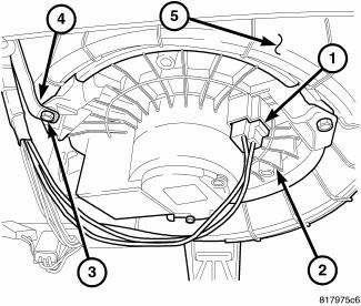
Fig. 141: Blower Motor-Removal/Installation
NOTE: LHD model shown. RHD model similar.
1. Position the blower motor (2) into the bottom of the HVAC housing (5).
2. Install the three screws (3) that secure the blower motor and the wire lead bracket (4) (if equipped) to the HVAC housing. Tighten the screws to 1.2 N.m (10 in. lbs.).
3. Connect the instrument panel wire harness connector (1) to the blower motor and engage the connector lock.
4. If equipped, install the silencer below the passenger side of the instrument panel.
5. Reconnect the negative battery cable.
 Diagnosis and Testing
BLOWER MOTOR
WARNING: Disable the airbag system before attempting any steering
wheel, steering
column, or instrument panel component diagnosis or service. Disconnect
and isolate the ...

See also:
Pad, heater
DESCRIPTION
Vehicles equipped with the optional heated seat system have two carbon fiber
heated seat elements located in
each front seat. One heating element is used for each seat cushion and anot ...
Installation
Fig. 186: Rear Heater AC Housing Removal/Installation
NOTE: MTC rear heater-A/C system shown. ATC system similar.
1. Position the rear heater-A/C housing (1) into the vehicle and align the
...
Switch, oil pressure
Description
The engine oil pressure switch is located on the right side of the engine
block. The switch screws into the
engine main oil gallery. The normally closed switch provides an input throug ...
