Dodge Journey: Installation
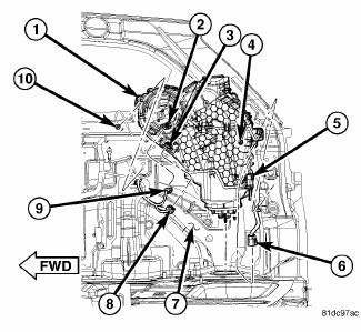
Fig. 186: Rear Heater AC Housing Removal/Installation
NOTE: MTC rear heater-A/C system shown. ATC system similar.
1. Position the rear heater-A/C housing (1) into the vehicle and align the guide pins on the housing to the holes in the right inner quarter panel (7).
2. Install the two bolts (4 and 10) that secure the rear heater-A/C housing to the right inner quarter panel.
Tighten the bolts to 3 N.m (27 in. lbs.).
3. Connect the body wire harness connector (6) to the rear heater-A/C wire harness connector (5).
4. Connect the body wire harness connectors (8 and 9) to the rear blower motor (2) and the rear blower motor resistor or power module (3) (depending on control system).
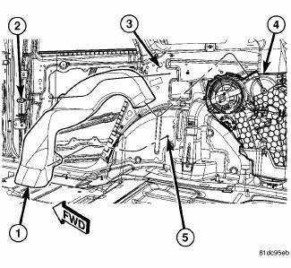
Fig. 187: Rear Floor Distribution Duct
5. Install the rear floor distribution duct (1) onto rear heater-A/C housing (4). Make sure the duct is fully engaged to the housing.
6. Engage the rear floor distribution duct to the stud (5) located on the right inner quarter panel (3).
7. Install the push-pin retainer (2) that secures the rear floor distribution duct to the right inner quarter panel.
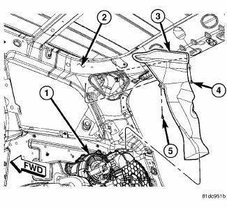
Fig. 188: Rear Ceiling Duct
8. Position the rear ceiling distribution duct (3) to the right D-pillar (2).
CAUTION: Use care when installing the rear ceiling distribution duct onto the heater-A/C housing to prevent damage to the molded plastic support brace located on the top of the housing outlet. Failure to follow this caution could result in part of, or all of the support brace falling into the rear housing, which may interfere with rear mode door operation.
9. Install the rear ceiling distribution duct onto the top of the rear heater-A/C housing (1). Make sure the duct is fully engaged to the housing.
10. Install the two retainers (4 and 5) that secure the rear ceiling distribution duct to the right D-pillar.
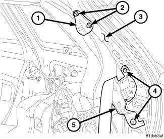
Fig. 189: D-Pillar Seat Belt Bracket
11. Position the upper seat belt bracket (2) onto the D-pillar (3) and install the two retaining bolts (1). Tighten the bolts to 52 N.m (38.5 ft. lbs.).
12. Install the right seat belt retractor (5) and retaining bolts (4) onto the D-pillar. Tighten the bolts to 52 N.m (38.5 ft. lbs.).
13. Install the right quarter trim panel. 14. Install the right D-pillar trim panel.
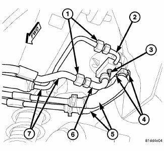
Fig. 190: Underbody Lines to Rear Housing
15. Raise and support the vehicle.
CAUTION: DO NOT apply excessive force on underbody heater lines or rear heater tubes fittings when connecting the connections. Excessive force may damage or deform the tubes and or lines, causing an engine coolant leak.
NOTE: Replacement of the rubber heater hose ends will be required if the rubber hoses were cut for removal.
16. Remove the tape or plugs from all the opened refrigerant line fittings and the rear expansion valve ports.
17. Lubricate new rubber O-ring seals with clean refrigerant oil and install them onto the underbody refrigerant extension line fittings. Use only the specified O-rings as they are made of a special material for the R-134a refrigerant system. Use only refrigerant oil of the type recommended for the A/C compressor in the vehicle.
18. Connect the underbody refrigerant extension lines and sealing plate (2 and 6) to the rear A/C expansion valve.
19. Loosely install the nut (3) that secures the extension lines and sealing plate to the rear A/C expansion valve.
20. Connect the underbody refrigerant lines (7) to the underbody refrigerant extension lines and tighten the fitting nuts (1) to 23 N.m (17 ft. lbs.).
21. Tighten the nut that secures the extension lines and sealing plate to the rear A/C expansion valve to 11 N.m (97 in. lbs.).
22. Connect the underbody heater lines (5) to the rear heater core tubes located behind the right rear wheel housing and engage the spring type hose clamps (4).
23. Lower the vehicle.
24. Reconnect the negative battery cable.
25. If the heater core is being replaced, flush the cooling system. 26. Fill the engine cooling system.
CAUTION: Do NOT run the engine with a vacuum pump in operation or with a vacuum present within the A/C system when equipped with the Denso 6SEU16 variable displacement compressor. Failure to follow this caution will result in serious A/C compressor damage.
27. Evacuate and charge the refrigerant system.
28. Calibrate the A/C-heater control.
 Assembly
CAUTION: Be certain to adjust the refrigerant oil level when
servicing the A/C
refrigerant system. Failure to properly adjust the refrigerant
oil level will prevent the A/C system fro ...
 Motor, blower, rear
DESCRIPTION
Fig. 191: Rear Blower
The rear blower motor (1) is a 12-volt, direct current (DC) motor mounted
within a plastic housing with an
integral wire connector (4) and a squirrel cage-type ...
See also:
Unit, heater
DESCRIPTION
Fig. 323: Positive Temperature Coefficient Heater - Description
NOTE: LHD model shown. RHD model similar.
An electric positive temperature coefficient (PTC) heater unit (1) is us ...
Assembly
HOUSING-AIR DISTRIBUTION
NOTE: LHD model with A/C shown in illustrations. RHD and heater-only
models similar.
Fig. 115: Mode Door Levers-Removal/Installation
1. If removed, install the fo ...
TIRE CHAINS
Due to limited clearance, tire chains are not recommended.
CAUTION:
Damage to the vehicle may result if tire chains are
used. ...
