Dodge Journey: Installation
2.7L ENGINE
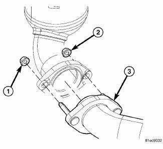
Fig. 32: Maniverter To Cross Under Fasteners
1. Install the cross under pipe (3). and the front maniverter-to-cross under fasteners (1) and (2). Tighten to 27 Nm (20 ft. lb.).
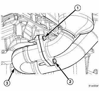
Fig. 33: Cross Under Pipe Fasteners
2. Install the rear maniverter-to-cross under pipe fasteners (1) and (2). Tighten to 29 Nm (21 ft. lb.).
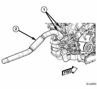
Fig. 34: 2.7L Extension Pipe
3. Install the exhaust extension pipe (2) to the cross under pipe, and install the fasteners (1). Tighten to 27 Nm (20 ft. lb.)
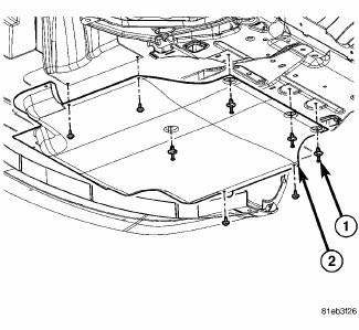
Fig. 35: Exhaust Extension Pipe
- -FASTENERS
- -BELLY PAN
4. Install the belly pan (2).
3.5L ENGINE
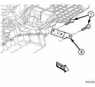
Fig. 36: Cross Under Bracket Transmission Bracket
1. If removed, install bracket (2). Tighten bolts (1) to 29 N.m (21 ft. lb.).
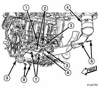
Fig. 37: Cross Under Pipe - 3.5L
- - BRACKET
- - BRACKET MOUNTING BOLTS
- - CROSS UNDER PIPE TO REAR MANIVERTER NUTS
- - REAR MANIVERTER
- - REAR MANIVERTER TO CROSS UNDER BOLTS
- - CROSS UNDER PIP TO BRACKET BOLTS
- - CROSS UNDER PIPE TO FRONT MANIVERTER NUTS
- - CROSS UNDER PIPE TO FRONT MANIVERTER BOLTS
- - FRONT MANIVERTER
2. Position cross under pipe.
3. Install cross under to rear maniverter bolts (5) and nuts (3). Tighten to 27 N.m (20 ft. lbs.).
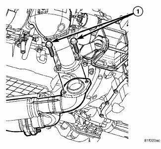
Fig. 38: Left Maniverter To Cross Under
4. Install cross under to front maniverter bolts and nuts. Tighten to 27 N.m (20 ft. lbs.).
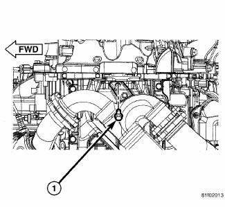
Fig. 39: Cross Under To Bracket
5. Install cross under pipe bracket to cross under pipe bolt (1). Tighten to 27 N.m (20 ft. lbs.).
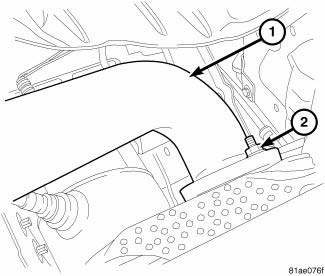
Fig. 40: Exhaust System Pipe
- - EXHAUST PIPE
- - NUTS
6. Install exhaust system pipe. Tighten flange nuts to 28 N.m (21 ft. lbs.).
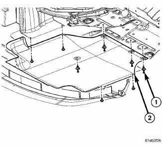
Fig. 41: Belly Pan
7. Install belly pan (2) and fasteners (1).
8. Lower vehicle.
9. Start the engine and inspect for exhaust leaks. Repair exhaust leaks as necessary.
10. Check the exhaust system for contact with the body panels. Make the necessary adjustments, if needed.
RESONATOR, EXHAUST
REMOVAL
EXHAUST RESONATOR
For removal of the exhaust resonator.
INSTALLATION
EXHAUST RESONATOR
For installation of the exhaust resonator.
 Removal
2.7L ENGINE
Fig. 22: Belly Pan
- BELLY PAN
- EXHAUST EXTENSION PIPE
1. Remove the belly pan (2).
Fig. 23: 2.7L Extension Pipe
2. Remove the fasteners (1), and remove the exhaust extens ...
 Sensor, exhaust pressure
REMOVAL
EXHAUST PRESSURE SENSOR
Fig. 42: DPF Components
- ELECTRICAL CONNECTOR
- PRESSURE DIFFERENTIAL SENSOR
- MOUNTING BOLT
- UPSTREAM PRESSURE TUBE
- DPF
- DOWNSTREAM PRESSURE TUB ...
See also:
Switch, backup lamp
DESCRIPTION
Fig. 43: Backup Lamp Switch
Vehicles equipped with a manual transmission (2) have a normally open,
spring-loaded plunger type backup
lamp switch (1). Vehicles with an optional elect ...
Diagnosis and testing
BATTERY
The battery must be completely charged and the terminals should be properly
cleaned and inspected before
diagnostic procedures are performed. See Cleaning for the proper battery
cleaning ...
Flow check
To determine whether coolant is flowing through the cooling system, use one
of the following procedures:
PREFERRED METHOD
WARNING: Do not remove the cooling system pressure cap or any hose ...
