Dodge Journey: Sensor, exhaust pressure
REMOVAL
EXHAUST PRESSURE SENSOR

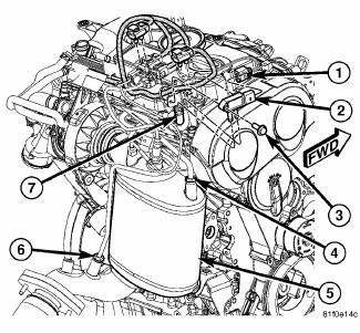
Fig. 42: DPF Components
- - ELECTRICAL CONNECTOR
- - PRESSURE DIFFERENTIAL SENSOR
- - MOUNTING BOLT
- - UPSTREAM PRESSURE TUBE
- - DPF
- - DOWNSTREAM PRESSURE TUBE
- - TUBING
INSTALLATION
EXHAUST PRESSURE SENSOR

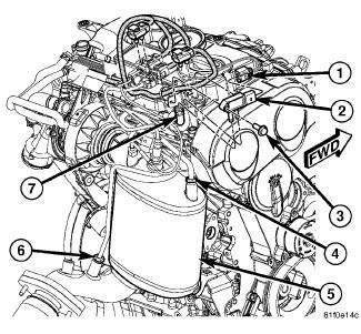
Fig. 43: DPF Components
- - ELECTRICAL CONNECTOR
- - PRESSURE DIFFERENTIAL SENSOR
- - MOUNTING BOLT
- - UPSTREAM PRESSURE TUBE
- - DPF
- - DOWNSTREAM PRESSURE TUBE
- - TUBING
1. Install tubing (7) on pressure differential sensor (2).
2. Position pressure differential sensor (2) and tubing (7).
3. Install pressure differential sensor mounting bolt (3). Tighten to 10 N.m (89 in. lbs.).
4. Install downstream pressure tube (6) into catalytic converter. Tighten the fitting to 10 N.m (89 in. lbs.).
5. Install upstream pressure tube (4) into catalytic converter. Tighten the fitting to 10 N.m (89 in. lbs.)
6. Position electrical connector (1) into bracket.
7. Connect negative battery cable.
 Installation
2.7L ENGINE
Fig. 32: Maniverter To Cross Under Fasteners
1. Install the cross under pipe (3). and the front maniverter-to-cross under
fasteners (1) and (2). Tighten to
27 Nm (20 ft. lb.).
Fi ...
 Sensor, exhaust temperature
REMOVAL
EXHAUST TEMPERATURE SENSOR
Fig. 44: Exhaust Temperature Sensor
- DPF TEMPERATURE SENSOR ELECTRICAL CONNECTOR
- DPF TEMPERATURE SENSOR
1. Remove engine cover.
2. Disconnect and ...
See also:
Fuel system
FUEL SYSTEM
Fuel System Similar Conditions Window - An indicator that 'Absolute MAP
When Fuel Sys Fail' and
'RPM When Fuel Sys Failed' are all in the same range when the failure
occurred. ...
Installation
LEFT-HAND-DRIVE
NOTE: The master cylinder must be bled before installing it on the
vehicle.
1. Bench bleed the master cylinder.
2. Wipe the face of the power brake booster clean where the ...
Removal
WARNING: Refer to the applicable warnings and cautions for this
system before
performing the following operation. Failure to follow the warnings and
cautions may result in possible se ...
