
Dodge Journey: Removal
WARNING: Refer to the applicable warnings and cautions for this system before performing the following operation. Failure to follow the warnings and cautions may result in possible serious or fatal injury.
CAUTION: Before removing the A/C condenser, note the location of each of the radiator/condenser air seals. These air seals are used to direct air through the A/C condenser and radiator. The air seals must be reinstalled in their proper locations in order for the A/C and engine cooling systems to perform as designed.
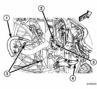
Fig. 222: Refrigerant Lines to Condenser Tapping Block
1. Disconnect and isolate the negative battery cable.
2. Recover the refrigerant from the refrigerant system.
3. Remove the nuts (5) that secure the A/C discharge line (1) and the A/C liquid line (4) to the tapping block (2) located on the right side of the A/C condenser.
4. Disconnect the A/C discharge and liquid lines from the tapping block and remove and discard the O-ring seals and gaskets.
5. Remove the bolt (3) that secures the tapping block to the right side of the radiator support.
6. Install plugs in, or tape over the opened refrigerant line fittings and condenser ports.
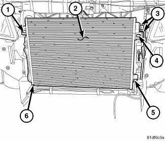
Fig. 223: Condenser Removal/Installation
NOTE: A/C condenser with automatic transmission cooler shown. A/C Condenser without cooler similar.
7. Remove the front fascia.
8. Remove the front bumper reinforcement.
9. If equipped, disconnect the automatic transmission cooler lines (3) from the left side of the A/C condenser (2).
10. If equipped with the 2.0L diesel engine, remove the charge air cooler.
11. Disengage the two plastic retaining tabs (1 and 4) that secure the top mounting brackets of the A/C condenser to the radiator.
12. Lift the A/C condenser slightly upward to disengage the two lower mounting brackets (5 and 6) from the condenser and remove the condenser from the engine compartment.
 Description, Operation
DESCRIPTION
Fig. 221: Condenser Description
NOTE: A/C condenser with automatic transmission cooler shown. A/C
Condenser
without cooler similar.
The A/C condenser (1) is located in the f ...
 Installation
CAUTION: Be certain to adjust the refrigerant oil level when
servicing the A/C
refrigerant system. Failure to properly adjust the refrigerant
oil level will prevent the A/C system fro ...
See also:
Installation
CLUTCH - FIXED DISPLACEMENT A/C COMPRESSOR
NOTE: Typical A/C compressor and clutch assembly shown in
illustrations.
Fig. 214: Clutch Coil & Snap Ring
1. Align the dowel pin on the bac ...
Engine diagnosis
ENGINE DIAGNOSIS - INTRODUCTION
Engine diagnosis is helpful in determining the causes of malfunctions not
detected and remedied by routine
maintenance.
These malfunctions may be classified as e ...
A/C Performance
The A/C system is designed to provide the passenger compartment with low
temperature and low humidity air.
The A/C evaporator, located in the HVAC housing is cooled to temperatures near
the fre ...
