Dodge Journey: Installation
CAUTION: Be certain to adjust the refrigerant oil level when servicing the A/C refrigerant system. Failure to properly adjust the refrigerant oil level will prevent the A/C system from operating as designed and can cause serious A/C compressor damage.
NOTE: When replacing multiple A/C system components, refer to the REFRIGERANT OIL CAPACITIES to determine how much oil should be added to the refrigerant system. NOTE: If only the A/C condenser is being replaced, add 10 milliliters (0.3 fluid ounce) of refrigerant oil to the refrigerant system. Use only refrigerant oil of the type recommended for the A/C compressor in the vehicle.
NOTE: Replacement of the refrigerant line O-ring seals and gaskets is required anytime a refrigerant line is disconnected. Failure to replace the rubber O-ring seals and metal gaskets could result in a refrigerant system leak.
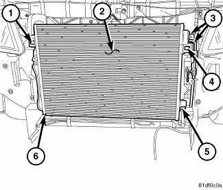
Fig. 224: Condenser Removal/Installation
NOTE: A/C condenser with automatic transmission cooler shown. A/C Condenser without cooler similar.
1. Position the A/C condenser (1) to the front of the engine compartment and engage the condenser to the two lower mounting brackets.
2. Engage the two plastic retaining tabs (1 and 4) that secure the top mounting brackets of the A/C condenser to the radiator. Make sure the retaining tabs are fully engaged.
3. If equipped, connect the automatic transmission cooler lines (2) to the left side of the A/C condenser.
4. If equipped with the 2.0L diesel engine, install the charge air cooler.
5. Install the front bumper reinforcement.
6. Install the front fascia.
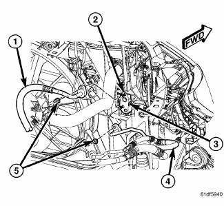
Fig. 225: Refrigerant Lines to Condenser Tapping Block
7. Install the bolt (3) that secures the condenser tapping block (2) to the right side of the radiator support.
Tighten the bolt securely.
8. Remove the tape or plug from the opened refrigerant line fittings and condenser ports.
9. Lubricate new rubber O-ring seals with clean refrigerant oil and install them and new gaskets onto the refrigerant line fittings. Use only the specified O-rings as they are made of a special material for the R- 134a system. Use only refrigerant oil of the type recommended for the A/C compressor in the vehicle.
10. Connect the A/C liquid line (4) and the A/C discharge line (1) to the tapping block and install the retaining nuts (5). Tighten the nuts to 20 N.m (15 ft. lbs.).
11. Reconnect the negative battery cable.
CAUTION: Do NOT run the engine with a vacuum pump in operation or with a vacuum present within the A/C system when equipped with the Denso 6SEU16 variable displacement compressor. Failure to follow this caution will result in serious A/C compressor damage.
12. Evacuate the refrigerant system.
13. If the A/C condenser is being replaced, add 10 milliliters (0.3 fluid ounce) of refrigerant oil to the refrigerant system. When replacing multiple A/C system components, refer to the REFRIGERANT OIL CAPACITIES to determine how much oil should be added to the refrigerant system. Use only refrigerant oil of the type recommended for the A/C compressor in the vehicle.
14. Charge the A/C system.
 Removal
WARNING: Refer to the applicable warnings and cautions for this
system before
performing the following operation. Failure to follow the warnings and
cautions may result in possible se ...

See also:
Assembly
Fig. 65: Remove Input Shaft Bearing Cup
NOTE: Always use ATF on all moving parts during this assembly
procedure.
1. Use Bearing Cup Remover 9664 (2) and appropriate Slide Hammer (1) to
r ...
ELECTRONIC BRAKE CONTROL SYSTEM
Your vehicle is equipped with an advanced electronic
brake control system commonly referred to as ESP. This
system includes Anti-Lock Brake System (ABS), Brake
Assist System (BAS), Traction Control ...
Diagnosis and Testing
REFRIGERANT SYSTEM LEAKS
WARNING: R-134a service equipment or vehicle A/C system should not
be pressure
tested or leak tested with compressed air. Mixture of air and R-134a can
be co ...
