Dodge Journey: Sensor, exhaust temperature
REMOVAL
EXHAUST TEMPERATURE SENSOR
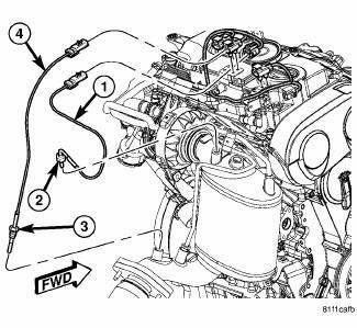
Fig. 44: Exhaust Temperature Sensor
- - DPF TEMPERATURE SENSOR ELECTRICAL CONNECTOR
- - DPF TEMPERATURE SENSOR
1. Remove engine cover.
2. Disconnect and isolate negative battery cable.
3. Disconnect upstream DPF temperature sensor electrical connector (1).
4. Remove upstream DPF temperature sensor (2).
5. Disconnect downstream DPF temperature sensor electrical connector (4).
6. Remove downstream DPF temperature sensor (3).
INSTALLATION
EXHAUST TEMPERATURE SENSOR

Fig. 45: Exhaust Temperature Sensor
- - DPF TEMPERATURE SENSOR ELECTRICAL CONNECTOR
- - DPF TEMPERATURE SENSOR
1. Position DPF downstream temperature sensor (3) into DPF. Tighten to 25 N.m (18 ft. lbs.).
2. Connect downstream temperature sensor electrical connector (4).
3. Position DPF upstream temperature sensor (2) into DPF. Tighten to 25 N.m (18 ft. lbs.).
4. Connect upstream temperature sensor electrical connector (1).
5. Install engine cover.
6. Connect negative battery cable.
SHIELD, HEAT
DESCRIPTION
The exhaust system heat shields are attached to the under body of the vehicle.
OPERATION
Heat shields are needed to protect both the vehicle and the environment from the high temperatures developed near the catalytic converter.
Avoid application of rust prevention compounds or undercoating materials to exhaust system floor pan heat shields on vehicles so equipped. Light over spray near the edges is permitted. Application of coating will greatly reduce the efficiency of the heat shields resulting in excessive floor pan temperatures and objectionable fumes.
 Sensor, exhaust pressure
REMOVAL
EXHAUST PRESSURE SENSOR
Fig. 42: DPF Components
- ELECTRICAL CONNECTOR
- PRESSURE DIFFERENTIAL SENSOR
- MOUNTING BOLT
- UPSTREAM PRESSURE TUBE
- DPF
- DOWNSTREAM PRESSURE TUB ...
 Ignition Control
...
See also:
Removal
LEFT-HAND-DRIVE
1. Disconnect and isolate the battery negative cable from its post on the
battery.
2. If equipped, remove the silencer pad below the steering column opening cover.
Fig. 132: S ...
Description, Operation
DESCRIPTION
Fig. 272: Rear Heater Core Description
The rear heater core (1) is located in the rear heater-A/C housing behind the
right interior quarter trim panel.
The rear heater core is a h ...
Lines, A/C underbody, extension
Description
Fig. 310: Underbody A/C Extension Lines Description
Models equipped with the rear heating-A/C system use metal lines attached to
the vehicle underbody to carry
refrigerant and engin ...
