Dodge Journey: Ensioner, belt
Removal
2.4L ENGINE
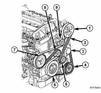
Fig. 36: ACCESSORY DRIVE BELT - WORLD ENGINE
- - POWER STEERING PUMP
- - ACCESSORY DRIVE BELT
- - GENERATOR
- - CRANKSHAFT PULLEY
- - LOWER IDLER PULLEY
- - CRANKSHAFT PULLEY
- - WATER PUMP PULLEY
- - ACCESSORY DRIVE BELT TENSIONER
- - UPPER IDLER PULLEY
1. Raise vehicle on hoist.
2. Remove belt splash shield.
3. Remove accessory drive belt (2).
4. Remove accessory drive belt tensioner mounting bolt. Remove accessory drive belt tensioner (8).
2.7L ENGINE
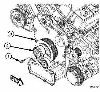
Fig. 37: ACCESSORY DRIVE BELT TENSIONER - 2.7L
- - BOLT
- - ACCESSORY DRIVE BELT TENSIONER
- - FRONT ENGINE COVER
WARNING: Because of high spring pressure, do not attempt to disassemble automatic tensioner. Unit is serviced as an assembly.
1. Remove accessory drive belt.
2. Remove accessory drive belt tensioner bolt (1).
3. Remove accessory drive belt tensioner (2) from front engine cover (3).
3.5L ENGINE
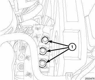
Fig. 38: ENGINE SUPPORT BRACKET BOLTS
WARNING: Because of high spring pressure, do not attempt to disassemble automatic tensioner. Unit is serviced as an assembly.
1. Remove the passenger side engine support bracket bolts (1).
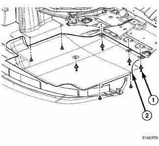
Fig. 39: BELLY PAN
2. Raise and support the vehicle.
3. Remove the accessory drive belt.
4. Remove the belly pan retainers (1).
5. Remove the belly pan (2).
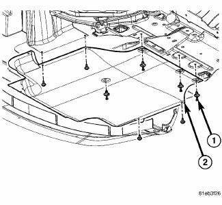
Fig. 40: ENGINE FORE/AFT CROSSMEMBER
6. Support the engine fore/aft crossmember (2) with an appropriate stand (1).
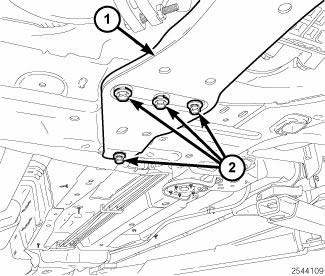
Fig. 41: REAR BOLTS & FORE/AFT CROSSMEMBER
7. Loosen the rear bolts (2) from the fore/aft crossmember (1).
8. Remove the front bolts from the fore/aft crossmember.
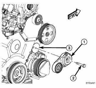
Fig. 42: ACCESSORY DRIVE BELT TENSIONER - 3.5L
- - ACCESSORY DRIVE BELT TENSIONER
- - BOLT
- - FRONT ENGINE COVER
9. Lower the stand supporting the fore/aft crossmember approximately 3/4" to 1".
10. Remove the tensioner assembly bolt (2).
11. Remove the accessory drive belt tensioner (1) from the vehicle.
2.0L DIESEL
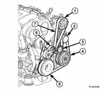
Fig. 43: 2.0L DIESEL ACCESSORY DRIVE BELT
- - P/S PULLEY
- - GENERATOR PULLEY
- - IDLER PULLEY
- - A/C COMPRESSOR
- - CRANKSHAFT PULLEY
- - ACCESSORY DRIVE BELT TENSIONER
- - ACCESSORY DRIVE BELT
1. Remove accessory drive belt.
2. Remove accessory drive belt tensioner mounting bolts.
3. Remove accessory drive belt tensioner (6)
Installation
2.4L ENGINE
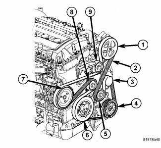
Fig. 44: ACCESSORY DRIVE BELT - WORLD ENGINE
- - POWER STEERING PUMP
- - ACCESSORY DRIVE BELT
- - GENERATOR
- - CRANKSHAFT PULLEY
- - LOWER IDLER PULLEY
- - CRANKSHAFT PULLEY
- - WATER PUMP PULLEY
- - ACCESSORY DRIVE BELT TENSIONER
- - UPPER IDLER PULLEY
1. Position accessory drive belt tensioner (8) and install mounting bolt. Tighten bolt to 24 N.m (212 in. lbs.).
2. Install accessory drive belt (2).
3. Install belt splash shield 4. Lower vehicle.
2.7L ENGINE
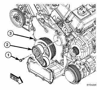
Fig. 45: ACCESSORY DRIVE BELT TENSIONER - 2.7L
- - BOLT
- - ACCESSORY DRIVE BELT TENSIONER
- - FRONT ENGINE COVER
1. Position accessory drive belt tensioner (2).
2. Install tensioner mounting bolt (1). Tighten bolt (1) to 34 N.m (40 ft. lbs.).
3. Install accessory drive belt.
3.5L ENGINE
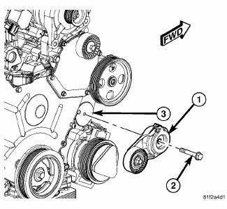
Fig. 46: ACCESSORY DRIVE BELT TENSIONER - 3.5L
1. Position the accessory drive belt tensioner (1) on the front engine cover (3).
2. Install the mounting bolt (2). Tighten the bolt to 41 N.m (30 ft. lbs.).
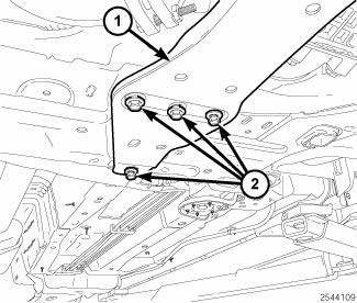
Fig. 47: REAR BOLTS & FORE/AFT CROSSMEMBER
3. Raise the fore/aft crossmember (1) approximately 3/4" to 1".
4. Install the front fore/aft crossmember bolts. Tighten the bolts to 55 N.m (41 ft. lbs.).
5. Tighten the rear fore/aft crossmember bolts (2) to 55 N.m (41 ft. lbs.).
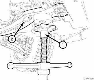
Fig. 48: ENGINE FORE/AFT CROSSMEMBER
6. Remove the stand (1) from the fore/aft crossmember (2).
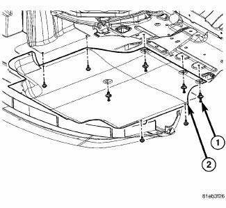
Fig. 49: BELLY PAN
7. Install the belly pan (2).
8. Install accessory drive belt.
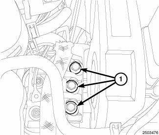
Fig. 50: ENGINE SUPPORT BRACKET BOLTS
9. Lower the vehicle.
10. Install the three bolts (1) at the passenger side engine support bracket. Tighten the bolts to 45 N.m (33 ft.lbs.)
2.0L DIESEL
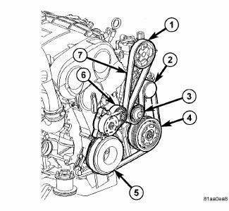
Fig. 51: 2.0L DIESEL ACCESSORY DRIVE BELT
- - P/S PULLEY
- - GENERATOR PULLEY
- - IDLER PULLEY
- - A/C COMPRESSOR
- - CRANKSHAFT PULLEY
- - ACCESSORY DRIVE BELT TENSIONER
- - ACCESSORY DRIVE BELT
1. Position accessory drive belt tensioner (6).
2. Install mounting bolts. Tighten bolts to 28 N.m (250 in. lbs.).
3. Install accessory drive belt.
 Pulley, idler
Removal
2.4L ENGINE
Fig. 30: ACCESSORY DRIVE BELT IDLER PULLEY - 2.4L
- UPPER PULLEY
- LOWER PULLEY
1. Remove accessory drive belt.
2. Remove upper idler pulley (1) and bolt.
3. Re ...
 Engine
...
See also:
Description
Fig. 1: Exterior Lighting System
The exterior lighting system for this vehicle includes the following exterior
lamp units:
Center High Mounted Stop Lamp (3) - A standard equipment Center High ...
Lens, instrument cluster
REMOVAL
Fig. 8: Instrument Cluster Lens Locking Tabs
1. Remove instrument cluster from vehicle. See Removal .
2. Separate the lens from the cluster by gently prying on the locking clips (1)
a ...
Removal
1. Raise and support vehicle.
NOTE: Perform 2 through 5 on each side of vehicle to complete pad set
removal.
Fig. 124: TIRE AND WHEEL MOUNTING
2. Remove wheel mounting nuts (3), then tire ...
