Dodge Journey: Standard procedure
SPIRAL CELL BATTERY CHARGING
WARNING: Never exceed 14.4 volts when charging a spiral cell battery. Personal injury and/or battery damage may result.
Vehicles equipped with a diesel engine utilize a unique spiral cell battery. This battery has a maximum charging voltage that must not be exceeded in order to restore the battery to its full potential, failure to use the following spiral cell battery charging procedure could result in damage to the battery or personal injury.
Battery charging is the means by which the battery can be restored to its full voltage potential. A battery is fully-charged when:
- OTC One Step Battery Analyzer and Charger special tool number OT-3641 or equivalent tester indicates battery is OK.
- Open-circuit voltage of the battery is 12.65 volts or above.
- Battery passes Load Test multiple times.
WARNING: If the battery shows signs of freezing, leaking, loose posts or low electrolyte level, do not test, assist-boost, or charge. The battery may arc internally and explode. Personal injury and/or vehicle damage may result.
WARNING: Explosive hydrogen gas forms in and around the battery. Do not smoke, use flame, or create sparks near the battery. Personal injury and/or vehicle damage may result.
WARNING: The battery contains sulfuric acid, which is poisonous and caustic. Avoid contact with the skin, eyes, or clothing. In the event of contact, flush with water and call a physician immediately. Keep out of the reach of children.
CAUTION: Always disconnect and isolate the battery negative cable before charging a battery. Charge the battery directly at the battery terminals. Do not exceed 14.4 volts while charging a battery.
CAUTION: The battery should not be hot to the touch. If the battery feels hot to the touch, turn off the charger and let the battery cool before continuing the charging operation. Damage to the battery may result.
After the battery has been charged to 12.6 volts or greater, perform a load test to determine the battery cranking capacity. If the battery passes a load test, return the battery to service. If the battery fails a load test, it is faulty and must be replaced.
Clean and inspect the battery hold downs, tray, terminals, posts, and top before completing battery service. See Cleaning for the proper battery system cleaning procedures. See Inspection for the proper battery system inspection procedures.
CHARGING A COMPLETELY DISCHARGED SPIRAL CELL BATTERY
WARNING: Never exceed 14.4 volts when charging a spiral cell battery. Personal injury and/or battery damage may result.
The following procedure should be used to recharge a completely discharged battery. Unless this procedure is properly followed, a good battery may be needlessly replaced.
Fig. 8: Voltmeter
1. Measure the voltage at the battery posts with a voltmeter, accurate to 1/10 (0.10) volt. If the reading is below ten volts, the battery charging current will be low. It could take several hours before the battery accepts a current greater than a few milliamperes. Such low current may not be detectable on the ammeters built into many battery chargers.
2. Disconnect and isolate the battery negative cable. Connect the OTC One Step Battery Analyzer and Charger special tool number OT-3641 or equivalent.
NOTE: Some battery chargers are equipped with polarity-sensing circuitry. This circuitry protects the battery charger and the battery from being damaged if they are improperly connected. If the battery state-of-charge is too low for the polarity-sensing circuitry to detect, the battery charger will not operate. This makes it appear that the battery will not accept charging current. See the instructions provided by the manufacturer of the battery charger for details on how to bypass the polarity-sensing circuitry.
3. Battery chargers vary in the amount of voltage and current they provide. The amount of time required for a battery to accept measurable charging current at various voltages is shown in SPIRAL CELL BATTERY CHARGE RATE TABLE . If the charging current is still not measurable at the end of the charging time, the battery is faulty and must be replaced. If the charging current is measurable during the charging time, the battery may be good and the charging should be completed in the normal manner.
SPIRAL CELL BATTERY CHARGE RATE TABLE

CHARGING TIME REQUIRED
The time required to charge a battery will vary, depending upon the following factors:
- Battery Capacity - A completely discharged heavy-duty battery requires twice the charging time of a small capacity battery.
- Temperature - A longer time will be needed to charge a battery at -18º C
(0º F) than at 27º C (80º F).
When a fast battery charger is connected to a cold battery, the current accepted by the battery will be very low at first. As the battery warms, it will accept a higher charging current rate (amperage).
- Charger Capacity - A battery charger that supplies only five amperes will require a longer charging time. A battery charger that supplies eight amperes will require a shorter charging time.
- State-Of-Charge - A completely discharged battery requires more charging time than a partially discharged battery. Electrolyte is nearly pure water in a completely discharged battery. At first, the charging current (amperage) will be low. As the battery charges, the specific gravity of the electrolyte will gradually rise.
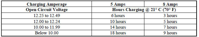
The Battery Charging Time Table gives an indication of the time required to charge a typical battery at room temperature based upon the battery state-of-charge and the charger capacity.
SPIRAL CELL BATTERY CHARGE TIME TABLE
CONVENTIONAL BATTERY CHARGING
CAUTION: Vehicles equipped with a diesel engine utilize a unique spiral cell battery.
This battery has a maximum charging voltage that must be used in order to restore the battery to its full potential, failure to use the spiral cell battery charging procedure could result in damage to the battery or personal injury.
Battery charging is the means by which the battery can be restored to its full voltage potential. A battery is fully-charged when:
- Micro 420 battery tester indicates battery is OK.
- Open-circuit voltage of the battery is 12.65 volts or above.
- Battery passes Load Test multiple times.
WARNING: If the battery shows signs of freezing, leaking, loose posts, do not test, assist-boost, or charge. The battery may arc internally and explode.
Personal injury and/or vehicle damage may result.
WARNING: Explosive hydrogen gas forms in and around the battery. Do not smoke, use flame, or create sparks near the battery. Personal injury and/or vehicle damage may result.
WARNING: The battery contains sulfuric acid, which is poisonous and caustic. Avoid contact with the skin, eyes, or clothing. In the event of contact, flush with water and call a physician immediately. Keep out of the reach of children.
WARNING: If the battery is equipped with removable cell caps, be certain that each of the cell caps is in place and tight before the battery is returned to service.
Personal injury and/or vehicle damage may result from loose or missing cell caps.
CAUTION: Always disconnect and isolate the battery negative cable before charging a battery. Do not exceed sixteen volts while charging a battery. Damage to the vehicle electrical system components may result.
CAUTION: Battery electrolyte will bubble inside the battery case during normal battery charging. Electrolyte boiling or being discharged from the battery vents indicates a battery overcharging condition. Immediately reduce the charging rate or turn off the charger to evaluate the battery condition.
Damage to the battery may result from overcharging.
CAUTION: The battery should not be hot to the touch. If the battery feels hot to the touch, turn off the charger and let the battery cool before continuing the charging operation. Damage to the battery may result.
After the battery has been charged to an open-circuit voltage reading of 12.4 volts or greater, retest the battery with the Micro 420 tester or perform a load test to determine the battery cranking capacity. See Standard Procedure for the proper battery test procedures. If the battery passes a load test, return the battery to service. If the battery fails a load test, it is faulty and must be replaced.
Clean and inspect the battery hold downs, tray, terminals, posts, and top before completing battery service. See Cleaning for the proper battery system cleaning procedures. See Inspection for the proper battery system inspection procedures.
CHARGING A COMPLETELY DISCHARGED CONVENTIONAL BATTERY
The following procedure should be used to recharge a completely discharged battery. Unless this procedure is properly followed, a good battery may be needlessly replaced.
Fig. 9: Identifying Battery Load Tester
1. Measure the voltage at the battery posts with a voltmeter, accurate to 1/10 (0.10) volt. If the reading is below ten volts, the battery charging current will be low. It could take some time before the battery accepts a current greater than a few milliamperes. Such low current may not be detectable on the ammeters built into many battery chargers.
2. Disconnect and isolate the battery negative cable. Connect the battery charger leads. Some battery chargers are equipped with polarity-sensing circuitry. This circuitry protects the battery charger and the battery from being damaged if they are improperly connected. If the battery state-of-charge is too low for the polarity-sensing circuitry to detect, the battery charger will not operate. This makes it appear that the battery will not accept charging current. See the instructions provided by the manufacturer of the battery charger for details on how to bypass the polarity-sensing circuitry.
3. Battery chargers vary in the amount of voltage and current they provide. The amount of time required for a battery to accept measurable charging current at various voltages is shown in the CONVENTIONAL BATTERY CHARGE RATE TABLE . If the charging current is still not measurable at the end of the charging time, the battery is faulty and must be replaced. If the charging current is measurable during the charging time, the battery may be good and the charging should be completed in the normal manner.
CONVENTIONAL BATTERY CHARGE RATE TABLE


CHARGING TIME REQUIRED
The time required to charge a battery will vary, depending upon the following factors:
- Battery Capacity - A completely discharged heavy-duty battery requires twice the charging time of a small capacity battery.
- Temperature - A longer time will be needed to charge a battery at -18º C
(0º F) than at 27º C (80º F).
When a fast battery charger is connected to a cold battery, the current accepted by the battery will be very low at first. As the battery warms, it will accept a higher charging current rate (amperage).
- Charger Capacity - A battery charger that supplies only five amperes will require a longer charging time. A battery charger that supplies twenty amperes or more will require a shorter charging time.
- State-Of-Charge - A completely discharged battery requires more charging time than a partially discharged battery. Electrolyte is nearly pure water in a completely discharged battery. At first, the charging current (amperage) will be low. As the battery charges, the specific gravity of the electrolyte will gradually rise.
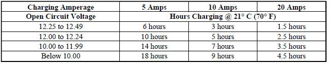
The Conventional Battery Charging Time Table gives an indication of the time required to charge a typical battery at room temperature based upon the battery state-of-charge and the charger capacity.
CONVENTIONAL BATTERY CHARGING TIME TABLE
USING MICRO 420 BATTERY TESTER (GASOLINE ENGINES)
Fig. 10: Identifying Micro Battery Tester
NOTE: The Micro 420 battery tester should only be used to test vehicles equipped with gasoline engines. If the vehicle being tested has a diesel engine the OTC, One Step Battery Analyzer and Charger (OTC) special tool number OT-3641 or equivalent should be used to test the battery.
Always use the Micro 420 instruction manual that was supplied with the tester as a reference. If the instruction manual is not available the following procedure can be used:
WARNING: Always wear appropriate eye protection and use extreme caution when working with batteries. Failure to do so may result in serious or fatal injury.
BATTERY TESTING
1. If testing the battery out of vehicle, clean the battery terminals with a wire brush before testing. If the battery is equipped with side post terminals, install and tighten the supplied lead terminal stud adapters.
Do not use steel bolts. Failure to properly install the stud adapters or using stud adapters that are dirty or worn-out may result in false test readings.
2. If testing the battery in the vehicle, make certain all of the vehicle accessory loads are off, including the ignition.
3. Connect the tester to the battery, the red clamp to the positive (+) terminal and the black clamp to the negative (-) terminal.
NOTE: Multiple batteries connected in parallel must have the ground cable disconnected to perform a battery test. Failure to disconnect may result in false battery test readings.
4. Using the ARROW key select in or out of vehicle testing and press ENTER to make a selection.
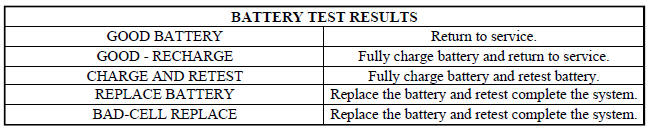
5. If not selected, choose the Cold Cranking Amp (CCA) battery rating. Or select the appropriate battery rating for your area (see menu). The tester then runs its self programmed test of the battery and display the results. Refer to the BATTERY TEST RESULTS chart.
CAUTION: If replacing the battery is the result of the test, this may mean a poor connection between the vehicle cables and battery exists. After disconnecting the vehicle battery cables from the battery, retest the battery using the out of vehicle test before replacing.
6. While viewing the battery test result, press the CODE button and the tester, prompts you for the last 4 digits of the VIN. Use the UP/DOWN arrow buttons to scroll to the correct character, then press ENTER to select and move to the next digit. Press the ENTER button to view the service code. Pressing the CODE button a second time returns you to the test results.
OPEN-CIRCUIT VOLTAGE TEST
A battery open-circuit voltage (no load) test will show the approximate state-of-charge of a battery.
Before proceeding with this test, completely charge the battery, refer to the appropriate battery charging procedure.
Fig. 11: Voltmeter
1. Before measuring the open-circuit voltage, the surface charge must be removed from the battery. Turn on the headlamps for fifteen seconds, then allow up to five minutes for the battery voltage to stabilize.
2. Disconnect and isolate both battery cables, negative cable first.
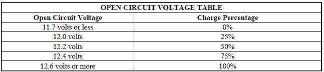
3. Using a voltmeter connected to the battery posts (see the instructions provided by the manufacturer of the voltmeter), measure the open-circuit voltage.
See the OPEN-CIRCUIT VOLTAGE chart. This voltage reading will indicate the battery state-of-charge, but will not reveal its cranking capacity. If a battery has an open-circuit voltage reading of 12.4 volts or greater, it may be load tested to reveal its cranking capacity.
IGNITION-OFF DRAW TEST
The term Ignition-Off Draw (IOD) identifies a normal condition where power is being drained from the battery with the ignition switch in the Off position. A normal vehicle electrical system will draw from five to thirty-five milliamperes (0.005 to 0.035 ampere) with the ignition switch in the Off position, and all non-ignition controlled circuits in proper working order. Up to thirty-five milliamperes are needed to enable the memory functions for the Powertrain Control Module (PCM), digital clock, electronically tuned radio, and other modules which may vary with the vehicle equipment.
A vehicle that has not been operated for approximately twenty days, may discharge the battery to an inadequate level. When a vehicle will not be used for twenty days or more (stored), remove the IOD fuse from the Totally Integrated Power Module (TIPM). This will reduce battery discharging.
Excessive IOD can be caused by:
- Electrical items left on.
- Faulty or improperly adjusted switches.
- Faulty or shorted electronic modules and components.
- An internally shorted generator.
- Intermittent shorts in the wiring.
If the IOD is over thirty-five milliamperes, the problem must be found and corrected before replacing a battery.
In most cases, the battery can be charged and returned to service after the excessive IOD condition has been corrected.
1. Verify that all electrical accessories are off. Turn off all lamps, remove the ignition key, and close all doors. If the vehicle is equipped with an illuminated entry system or an electronically tuned radio, allow the electronic timer function of these systems to automatically shut off (time out). This may take up to three minutes.
2. Determine that the underhood lamp is operating properly, then disconnect the lamp wire harness connector or remove the lamp bulb.
3. Disconnect the battery negative cable.
4. Set an electronic digital multi-meter to its highest amperage scale. Connect the multi-meter between the disconnected battery negative cable terminal clamp and the battery negative terminal post. Make sure that the doors remain closed so that the illuminated entry system is not activated. The multi-meter amperage reading may remain high for up to three minutes, or may not give any reading at all while set in the highest amperage scale, depending upon the electrical equipment in the vehicle. The multi-meter leads must be securely clamped to the battery negative cable terminal clamp and the battery negative terminal post. If continuity between the battery negative terminal post and the negative cable terminal clamp is lost during any part of the IOD test, the electronic timer function will be activated and all of the tests will have to be repeated.
5. After about three minutes, the high-amperage IOD reading on the multi-meter should become very low or nonexistent, depending upon the electrical equipment in the vehicle. If the amperage reading remains high, remove and replace each fuse or circuit breaker in the Totally Integrated Power Module (TIPM), one at a time until the amperage reading becomes very low, or nonexistent. This will isolate each circuit and identify the circuit that is the source of the high-amperage IOD. If the amperage reading remains high after removing and replacing each fuse and circuit breaker, disconnect the wire harness from the generator. If the amperage reading now becomes very low or nonexistent. After the high-amperage IOD has been corrected, switch the multi-meter to progressively lower amperage scales and, if necessary, repeat the fuse and circuit breaker remove-and-replace process to identify and correct all sources of excessive IOD. It is now safe to select the lowest milliampere scale of the multi-meter to check the low-amperage IOD.
CAUTION: Do not open any doors, or turn on any electrical accessories with the lowest milliampere scale selected, or the multi-meter may be damaged.
6. Observe the multi-meter reading. The low-amperage IOD should not exceed thirty-five milliamperes (0.035 ampere). If the current draw exceeds thirty-five milliamperes, isolate each circuit using the fuse and circuit breaker remove-and-replace process in 5. The multi-meter reading will drop to within the acceptable limit when the source of the excessive current draw is disconnected. Repair this circuit as required; whether a wiring short, incorrect switch adjustment, or a component failure is at fault.
 Diagnosis and testing
BATTERY
The battery must be completely charged and the terminals should be properly
cleaned and inspected before
diagnostic procedures are performed. See Cleaning for the proper battery
cleaning ...
 Removal, Installation
REMOVAL
WARNING: To protect the hands from battery acid, a suitable pair
of heavy duty
rubber gloves should be worn when removing or servicing a battery.
Safety glasses also should ...
See also:
REMOTE KEYLESS ENTRY (RKE)
This system allows you to lock or unlock the doors and
liftgate or activate the Panic Alarm from distances up to
approximately 66 ft (20 m) using a hand-held Key Fob
with Remote Keyless Entry (RKE) ...
Antenna, satellite, audio, video
ANTENNA, SATELLITE, AUDIO
DESCRIPTION
Fig. 3: Satellite Audio
If the vehicle is equipped with satellite audio, a combined antenna for AM/FM
and satellite is used. For
removal. See Removal and ...
Switch, ignition
DESCRIPTION
This vehicle is equipped with a Wireless Ignition Node (WIN). The WIN, along
with the FOB with Integrated
Key (FOBIK) are the primary components of the keyless ignition system. The onl ...
