Dodge Journey: Seal, input flange
REMOVAL
Fig. 80: Removing /Installing Propeller Shaft
NOTE: Rubber coupler is part of the propeller shaft assembly. Removing coupler from propeller shaft will result in vibration/balance issues.
1. Raise vehicle on hoist.
2. Apply alignment index marks (4) on the rear axle flange (5) and rubber coupler (1).
3. Remove three rear propeller shaft rubber coupler to rear axle input flange retaining bolts (3).
4. Slide propeller shaft (2) back off rear axle input flange (5) and move out of the way as needed.
Fig. 81: Pinion Flange Nut Removal/Installation
5. Using tool C-3281 (1), loosen input flange nut.
Fig. 82: Input Flange Nut Removal/Installation
- - NUT
6. Remove input flange nut (1), and discard.
Fig. 83: Input Flange Washer
- - WASHER
7. Remove input flange washer (1).
Fig. 84: Suitable Puller & Input Flange
8. Using suitable puller (2), remove input flange (1).
Fig. 85: Input Flange Seal Removal/Installation
- - SEAL
- - SCREWDRIVER
9. Using suitable screwdriver (2), remove input flange seal from overrunning clutch housing.
INSTALLATION
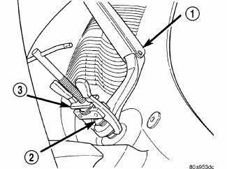
Fig. 86: Clutch Case
1. Using tool 9231A (1), install input flange seal to overrunning clutch case (2).
Fig. 87: Input Flange Shaft Seal
2. Install input flange shaft seal (1), on shaft threads at midway point of threads (2).
Fig. 88: Input Flange Removal/Installation
- - INPUT FLANGE
3. Install input flange (1).
Fig. 89: Input Flange Washer
- - WASHER
4. Install flange washer (1).
Fig. 90: Input Flange Nut Removal/Installation
- - NUT
5. Install new flange nut (1).
Fig. 91: Pinion Flange Nut Removal/Installation
6. Using tool C-3281 (2), torque flange nut to 135 N.m (100 ft. lbs.).
Fig. 92: Removing /Installing Propeller Shaft
7. Align marks (4) on propeller shaft rubber coupler (1) to rear axle input flange (5).
8. Install three rear propeller shaft to rear axle retaining bolts (3) and tighten to 58 N.m (43 ft. lbs.).
9. Lower vehicle.
 Fluid, differential
Standard Procedure
STANDARD PROCEDURE - DIFFERENTIAL ASSEMBLY FLUID CHANGE
Fig. 79: Differential Assembly Fluid Change
The drain plug (2) for the differential assembly is located in the bottom of ...
 Seal, output flange
REMOVAL
Fig. 93: Axle Seal Removal
- SEAL
- SCREWDRIVER
1. Raise vehicle on hoist.
2. Remove rear driveline module.
3. Use suitable screwdriver (2) to remove output seal (1).
INSTA ...
See also:
Installation
BULBS
HEADLAMP HIGH BEAM
CAUTION: Always use the correct bulb size and type for
replacement. An incorrect
bulb size or type may overheat and cause damage to the lamp, the socket
or ...
Driving clutches
DESCRIPTION
Fig. 350: Identifying Input Clutch Assembly
- INPUT SHAFT
- UNDERDRIVE CLUTCH
- OVERDRIVE CLUTCH
- REVERSE CLUTCH
- OVERDRIVE SHAFT
- UNDERDRIVE SHAFT
Three hydraulical ...
Sensor, variable line pressure
DESCRIPTION
Fig. 390: Identifying Variable Line Pressure Sensor
- PRESSURE CONTROL SOLENOID
- LINE PRESSURE SENSOR
- SHOULDER SCREW
- VARIABLE LINE PRESSURE HEADER
- MANUAL SHAFT
- SC ...
