Dodge Journey: Crossmember, front fore and aft
REMOVAL
1. Raise and support the vehicle.
2. If equipped, remove the engine belly pan.

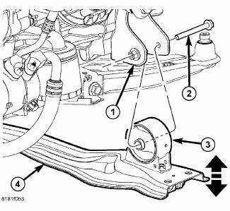
Fig. 29: Removing/Installing Fore/Aft Crossmember
3. Remove the front engine mount thru-bolt (2).

Fig. 30: Fore-Aft Crossmember Forward Mounting Bolts
4. Remove the fore-aft crossmember forward mounting bolts at the radiator support.
5. Remove the fore-aft crossmember rearward mounting bolts at the crossmember.
6. Remove the fore-aft crossmember.
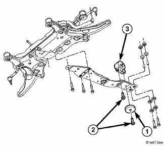
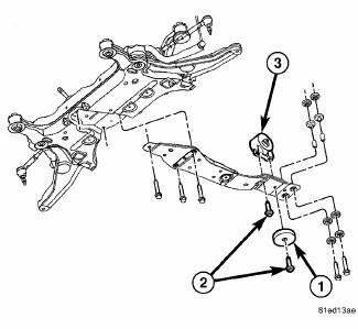
7. Remove the front engine mount mounting bolts (2) and damper (1). Remove the mount (3) from the crossmember.
INSTALLATION

Fig. 31: Fore-Aft Crossmember Forward Mounting Bolts
1. Install the front engine mount (3) on the crossmember. Install the mounting bolts (2) and damper (1).
Tighten the bolts to 50 N.m (37 ft. lbs.).
2. Position the fore-aft crossmember in the engine compartment and install the mounting bolts. Tighten the forward mounting bolts at the radiator support to 55 N.m (41 ft. lbs.). Tighten the rearward mounting bolts at the suspension crossmember to 55 N.m (41 ft. lbs.).

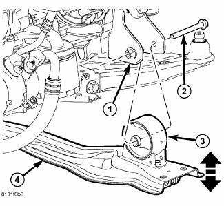
Fig. 32: Removing/Installing Fore/Aft Crossmember
3. Install the front engine mount thru-bolt (4). Tighten the bolt to 60 N.m (44 ft. lbs.).
4. If equipped, install the engine belly pan.
5. Lower the vehicle.
 Frame
Frame
SPECIFICATIONS
FRAME DIMENSIONS
Frame dimensions are listed in metric scale. All dimensions are from center
to center of Principal Locating
Point (PLP), or from center to center of PLP and fasten ...
 Crossmember, front suspension
REMOVAL
1. Raise and support the vehicle.
Fig. 33: Tire And Wheel Mounting
2. On each side of the vehicle, remove the wheel mounting nuts (3), then the
front tire and wheel assembly
(1).
Fi ...
See also:
Cover(s), cylinder head, left
REMOVAL
1. Disconnect negative battery cable.
2. Disconnect electrical connectors from ignition coils and capacitor.
Reposition electrical harness.
3. Remove ground strap from cylinder head c ...
Installation
CAUTION: Be certain to adjust the refrigerant oil level when
servicing the A/C
refrigerant system. Failure to properly adjust the refrigerant
oil level will prevent the A/C system fro ...
Assembly
Fig. 239: Output Shaft #2 & Needle Bearing
1. Install the reverse needle bearing (1) onto the output shaft # 2 (2).
Fig. 240: Synchronizer
NOTE: Pay attention to the direction when inser ...
